Tuesday, 6 September 2016

Unconventional Offshore Structures-Wind Farms


Offshore Structures have been one of the most indigenous creations of man as it gave him access to the nature’s treasury of fuel and mineral reserves present in ample amounts underneath the oceans. A very important objective behind offshore structures is that man still has his limitations at land. Venturing into the oceans for the quest of abundant resources which were by far, unavailable or scanty in land can meet most of his needs.


Figure 1. Illustration of offshore extraction ( Courtesy: www.googleimages.com)


With various types, their research and development needs a lot of work force and statistical data. Different parts of ocean have different kind of weather and wave pattern to which an offshore structure is subjected. The external forces includes waves, wind, currents and corrosion along with other environmental vagaries.We know these structures are built at higher stakes and thus must reciprocate greater revenues which needs the efficiency to be maximum.


So far we had known of conventional ones like Jacket Platforms, Rigs, Drill ships, Spars, FPSOs, TLPs, Fixed or gravity based structures. These are segregated as: movable and immovable. Most of them are dedicated to more or less the same types of purpose: exploration, extraction, processing and/or transportation of petroleum and oil products derived from the deep sea reserves. A lot of analysis is done on them including strength calculations, advanced extraction techniques, software interpretations or safer installation-cum-maintenance goals.

Figure 2.: Conventional Oil Rig (Courtesy: www.offshoretechnology.com)

 
But have we ever wondered, can offshore structures be solely employed for the sake of exploiting resources that were limited or absent on land? Can they be utilized as improvements over infrastructure that are already present on land for better outcomes?


The answer lies in certain unconventional offshore structures such as wind farms, subsea pipelines, unconventional offshore gas stations or hydel-power installations which are focused mainly on tapping abundant 'oceanic' natural resources ( plentiful, renewable) for the purpose of generation of power on a widespread scale. As we are well aware of, renewable resources such as coal, natural gas and other earth derivatives are dwindling drastically. Thus to meet the insatiable needs of the ever-inflating population, Alternative forms of natural resources should be ingenuously exploited. Some of them are already materialized, but more needs to be done for achieving a global trend. 

Here we limit our discussion only to Offshore Wind Farms- a big trend setter . Later we take some of the others.

What are Offshore Wind Farms?


 Offshore Wind Farms are exemplary modern developments of tapping wind energy at seas for widespread harnessing of power as compared to landmass.


Figure 3: Offshore Wind Farm ( Copyright: www.tokyotimes.com)


Despite wind farms being relatively old technology on land, they have gained more credibility on seas in the recent years. Have you thought why?

The wind pattern on seas or vicinal to the shoreline is much more uniform, stronger and consistent as compared to that on land surface. Thus, this can be opportune in tapping wind energy on a much wider scale wielding more influence in generation of electrical power. According to a recent study by the United States Department of Energy, up to 50% of more power can be generated by an offshore wind installation than a land installation given the same turbine capacity. This is a boon actually for us! Given our vast ocean areas, if judiciously tapped, offshore wind farms can supplement a huge stake of our global energy demand.


The first offshore wind farm technology came up in Denmark in 1991. Since then, it is having a dramatic surge, especially in the Western frontiers. Till now about 4.5 GW of offshore wind installations are present worldwide, European countries being the maximum stakeholders and the Americas following close by. Around 30 GW is coming up and by 2020, an optimistic target of 75 GW is sighted. Major exploiters of them are Denmark, UK, Germany, US, Japan, China, South Korea, Belgium, Sweden, Portugal, Norway and Netherlands. India is also on the move with 100 MW planned along the Gujarat coast.


Requirements and Operation


Figure 4: Wind Farm (Copyright: www.theguardian.com)


Wind turbines convert the kinetic energy in the wind into mechanical power, which in turn generates electric power by induction. A generator can convert this mechanical power into electricity for commercial use. They are mostly designed for shallow waters, mostly continental shelf (preferably depths of 9-14 metres). Why?

  • Installation procedure is cheaper and easier  
  •    Moreover, building them on the continental shelf makes it relatively easier for drawing             transmission lines to the shore than from deep sea. 
  •   Maintenance can be done frequently and as and when required.
  •    Safeguard from adverse, unpredictable weather conditions deep sea.
  •   To avoid interference with the mid-ocean traffic. 

f     Now most of the offshore wind farms have a strong pile that is driven into the seabed. This  supports the nacelle and the tower. 


Figure 5: Nacelle of a Wind Farm installation (Courtesy :Wikipedia)


      The Nacelle is a shell adjoining the blades which houses the blade hub, rotor, generator, gearbox and the remaining electronic components.The Tower is the extension of the monopile and rises vertically above the waterline supporting the entire structure. The entire setup has a height of around 200 feet with additional 80-100 feet of piling foundations below the mud line. They are mostly three-bladed with the height of the farthest tip being up to 500 feet above seabed. Following image illustrates better.


Figure 6: (Courtesy: www.offshorewind.blz)


      The blades are similar to aircraft propeller blades (aerofoil sections) which are designed to turn in response to blowing air at a relevant speed and direction, which spin a drive shaft connected to a high-capacity generator producing electricity. Operational nameplate ratings of wind farms can vary from 2 to 5 MW (Find out about nameplate ratings).  

     After Production


Once the power is harnessed, it has to be distributed to the shore substations for further use. This is the most cumbersome thing in case of wind farms as contrary to the oil platforms (where fuel could be stored or transported through ships or subsea pipelines). One essential feature is the use of Electric Service Platforms (ESPs), which act like intermediate ‘offshore substations’! They are placed in a region within the radius of vicinal substations, or reckoned as the turbine array.  The power output from the turbines is transmitted through high tension undersea cables to the ESPs. These either store or transmit the power to the grid at shore, from where it is distributed elsewhere. Underlaying of subsea pipelines is a critical task and has to be done with precision, high design reliability and safety factors.That’s the prime reason for keeping the wind farms as much closer to the shore as possible (as we had discussed before). 
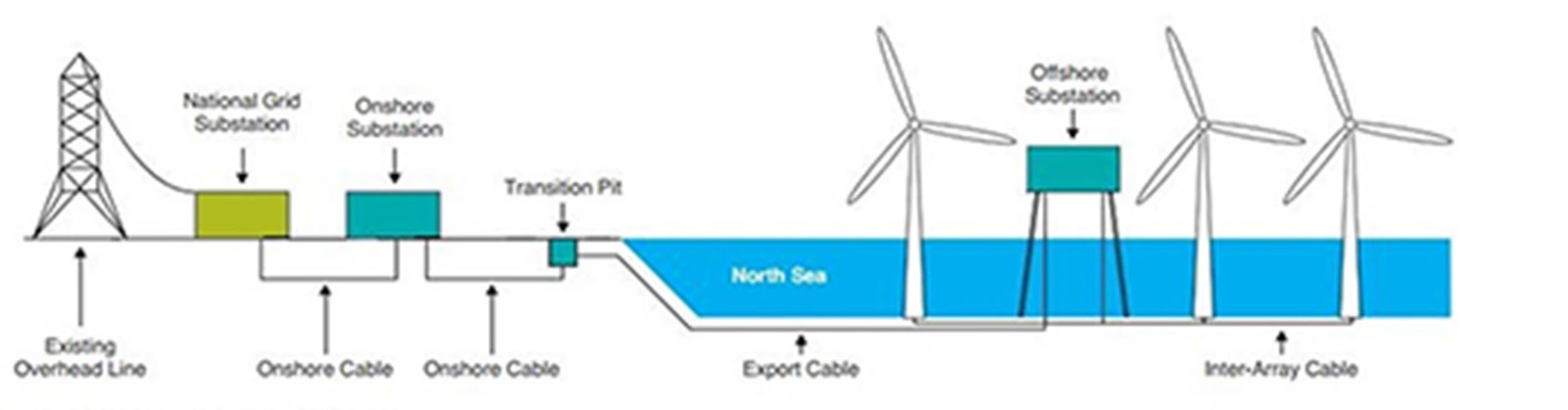

Figure 7: Distribution layout of an offshore wind farm(Courtesy: googleimages)


Figure 8: An Electric Service Platform (Courtesy: www.boem.gov)


 A big problem with these offshore wind farms is that they are constantly exposed to the ocean environment. Thus their design criterion and basis for modification is different from that of onshore or land-based structures. Let’s see some of them:

  • Assessment of the structural design criterion is a very difficult task as the loads on the sea are highly large and unpredictable. Prediction of the dynamic loads such as wave, wind, current, pressure loads are analysed in details. The climatic patterns or the predominant wave actions under variant sea states are studied in detail before installation.     
  •  A site-based design is done for the particular installation as unlike land, the environmental condition in the waters are highly non-uniform. Thus design should always have a ‘fit’ to the location of operation. Water depth, topography of seabed, salinity, geology of the type of underwater soil and other miscellaneous geotechnical details are studied before laying out the design. 
  • The pile foundation has to be penetrating deep into the seafloor and strong enough to withstand the uncertain loads encountered in the sea. The effect of all the six degrees of motion in water (surge, sway, heave, yaw, roll, pitch) are taken into account as for any marine structure.
  •  As the weather in oceans is highly varied, specialized internal climate control systems are employed to maintain proper conditions congenial to the operation of the components.
  • Measures for stability of the towers and its resistance to waves, wind or icing accretions is done.
  • Corrosion is a pressing issue in oceans. Thus higher grade paints along with other modern anti-corrosion measures are applied on these.
  • As maintenance is not that easy every time, automated greasing and drainage system is inbuilt into them. Self-heating and cooling systems are also employed.
  • Problems of navigation are also sometimes grave. Thus, apart from selection of leaner marine traffic sites for installation, they are also specially equipment with emitters for navigational safety. 
  • A high degree of precision is used for supply of power through lines post-production to the land-shore.

Figure 9: Often wind farms are a big problem to ship traffic

 Advantages and Disadvantages


Like it is said, everything has its pros and cons. Though wind farms have emerged to be one of the most ideal applications of oceanic exploitation for mass productions, it is facing challenges. However, on judicious planning advantages outweigh them.

Advantages:

ü   Primary advantages of wind power are that it is free, renewable, clean, non-polluting source of energy. 

ü  Land acquisition problems are eliminated.

ü  Constant wind to enable greater productivity.

ü  Facilitates port and harbour infrastructure. Also acts as the primary source of electricity in remote coastal villages.

     Disadvantages:
  •   Ecological problems to marine underwater life.
  •  Proximity of seabirds to get struck by.
  •  Very high initial investment
  •  Navigation  problems
  •  Tedious job of laying high-voltage underwater wires over long distances to the shore.
  •   Problems of fishing and trawling
  •   High noise and vibration created by installation and operations.
  •   Prone to damage by lightning or very adverse sea states 

     
      The potential of offshore wind is enormous. It could meet Europe's energy demand seven times over and United States energy demand four times over. In India too, it can supplement the shortfall power over a large number of regions, especially rural areas and large cities at the same time, where excess consumption often leads to crisis. Offshore wind power generating stations have a few advantages over the onshore ones like wind blows at a higher speed as we move far away from the shore so more power can be generated from few turbines. Most of the world's largest cities are located near a coastline avoiding the need of long transmission lines and constructing an offshore wind farm makes sense in a densely populated coastal region with high property value.


Figure 10: Some of the global statistics ( Courtesy: www.gwec.net)


      Presently only 3% of global installed capacity is offshore. Relatively high costs remains the biggest challenge for offshore wind development. But forgoing its problems and making it instrumental to meet the quantum of our short falling energy reserves. Also as we know, time is money. Thus, improper and slack utilization from the early stages can make any asset a liability.LSD

        
     Article by:   Kartik Garg


Friday, 25 March 2016

Dynamic Amplification and Extrapolation of Fundamental Laws


Study of the unpredictability of wave based phenomenon is of great importance in seakeeping.


We are accustomed to apply Newton’s Equations every now and then. But how much do we know its validity? If we seek the answer to this question, even the masterminds have to rack their brains! It is a universal and harsh truth that these are applicable to only a meager number of bodies around us.

Coming to the context of ships, Newton’s ‘linear’ postulates falter in front of the large diabolical forces and unpredictable rapidly-varying disturbances, it is subject to. If we take the pain to estimate the forces over a stipulated span of time on a side shell plating of the outer hull, we could notice that neither the strength, intensity, distribution nor the fetch of the generated stress can be estimated by our conventional methods. Dramatically enough, every single physical parameters associated with the region wields as an abrupt time-varying function. For example, the stress distribution would be following abrupt frequency response changes of intensity. This is where we introduce a non-dimensional parameter known as the Dynamic Amplification Factor. Mathematically, it can be expressed as the ratio of the maximum permissible load, Um to the static load applied to the same body, Us. Or in other words, it takes into account the “static-equivalent load” under the same conditions.


Rarely, in ships do we find static loads acting. The loading like that of storms, rain, earthquakes, floods or calmer ones like live traffic loads on a bridge, the loads encountered by a ship under all abrupt sea states are essentially highly accelerated and variant, viz. Dynamic loads. Have you ever wondered at the rogue deep sea waves lashing out at a ship? Do you think that the aggregate stresses embarked upon the ship at its multitude of structural locations could be simply assessed by a petty Newtonian Load equation? The answer is a big no. A lot of tedious work has to done by designers/naval architects, engineers, seafarers to analyse the nature of the loading at all strategic locations of any structure to execute its probabilistic failure computations.


The most preliminary application of Dynamic Amplification Factor on a ship would be to study the forces enacting on a single isolated object on board while a ship hurls above a big sea wave. This situation is analogous to the case of a simple elevator! We know that whenever an elevator goes upward with a certain acceleration, weight experienced by an object in it increases. Similarly, when a ship is aloft a wave, any object on board experiences an “added pseudo force”. 

Hence, the classical equation, F=mg gets modified in the form of

 F= m*g*(DYNAMIC AMPLIFICATION FACTOR)

The basic concept lies in the fact that when a body is subject to dynamic force, its effects are more pronounced due to the materials inability to promptly react to the sudden disturbance. This is where the induction of the DAF equalizes the effects of static and dynamic loading under the given conditions. 

The determination of the Dynamic Amplification Factor, however is a cumbersome task where it involves a compact knowledge of the nature of the frequency response curves.


Some of the methods involved are complicated and require high levels of expertise. Averaging of the stress variations from time-to-time in a system like that of a ship to deduce the DAF is a challenge to a naval architect. The designer/builder hones his skills again in turn to implement this in the detailed structural design and material analysis. Thus this simple ‘extrapolation’ of the fundamental laws have pronounced implications in the ship structure analysis.

By: Subhodeep Ghosh (Originally posted on our page)

Sunday, 6 March 2016

Under the Skin: Part 1


Have you ever wondered what lies within the skin of the prodigious engineering marvels such like ships? You may be surprised to learn that ships or vessels like we humans and other living creatures have an intricate 'skeleton' underneath! Analogous to the complex network of bones and ligaments in living beings, they have a well-engineered arrangement of structural members in varying attributes.


Fig. 1 A high-definition picture of Queen Mary 2 (Courtesy: www.largestships.com Archives)


You may still be in some doubt!

Large number of big and small components make up the hull structure which is the primary phase of manufacturing of any vessel and is the most tedious task. It is believed that the safety and sustainability of the vessel during its service is a chunk dependent on the ingenuity of the structural members and thereby the entire structure. Failure of any single component leads to disastrous results. So, it is a challenging task to undergo detailed selection, arrangement, analysis and testing methods to these structures.With due respect to the traditional mechanical analysis methods of materials along with empirical probabilistic methods,modern computational testing methods accompanied by Finite Element Analysis and other precision software have eased the cumber of the olden days providing a wider scope of accuracy and precision. 


SHIP'S HULL- AN OVERVIEW 

                    Fig.2 Cross-Sectional View of a General Cargo Carrier                
                                

A ship's hull is comprised of a criss-cross network of perpendicularly placed plates or members which are fixated to each other at all possible degrees of freedom. Some crucial members include extensive varieties of plates, struts, columns, bars, beams, stanchions, angles, brackets, knees, elbows and so on.

Must be wondering the arrangement of all of these in a mere vessel? And that too which floats and treads in water for such a long span of time!


The answer is quite simple. There is a holistic placement of all of them in accordance to their capabilities which complies with their strength, scantlings, locations, loads/stresses and their utilities. A ship, as we know is a large structure aimed at overcoming all hindrances of distance, carriage and cargo, sea-states, environmental vagaries, titanic loads accompanied by the pressing issue of safety of life as well as property (cargo/machinery). Naval architects, shipbuilders and designers owe a considerable amount of showmanship regarding design, lines plan, materials, scantlings, strength and model testings, intricate architecture of each component, related calculations and final accuracy in materialization of the arduous job. An obvious question arises at this juncture: What should be the apt choice for material selection as far as the hull is concerned? 


What is the material used?


Mild steel and wrought iron has been a sought-after choice of shipbuilders around the globe after the departure of the yesteryear wooden/timber vessels.However, in the recent times, wrought iron is losing its popularity owing to its corrosive nature and being bulkier.Mild steel earns the reputation of its abundance, ease in assemblage, lightweight along with required strength, ductility and malleability. However it is prone to failure under high stresses and hull shocks. It also has a degree of unreliability when it comes to their service as girders, struts or internal supporting members, with due respect to larger ships of today having massive tonnage. Furthermore it is highly corrosive in nature and is also prone to other problems like fouling. So, another breed of steel, High Tensile Steel/High Strength Steel with increased yield points have stolen the limelight. They include grades of steel like AH,DH,EH. Their yield point lies in the range of 315-350 MPa!


Fig.3: A very rare pic of The Titanic in construction. Wrought iron and mild steel were the chief materials used along with rivet joining (Courtesy: www.amberonline.com)     


But as it is said, everything has its pros and cons. High Steel Strength, despite its high degree of toughness has poor response when it comes to the problem of flexural bending. As longitudinal bending is inevitable in most of the large ocean-going vessels, they often pose the risk of fracture due to intensive bending moments at uncongenial sea states. The advent of composite fabricated members in the modern shipbuilding has changed the scenario. Though the SOLAS requirements and a majority of classification societies were dubious about its utility in the superstructures or other deck areas, thanks to its reduced fire resistance, the mid-1980s saw a gradual upraise of composite fibers in the industry. As usual, supporting reasons existed!


  • Lightweight. This helped in easily meeting the critical dead-weight barrier assigned to a ship. So this, up to a certain extent  helped in greater "inclusion" of added mass on board which was a constraint if material was a bulky one like steel. 
  • It has a lower life cycle cost coupled with cheaper maintenance and durability.
  • Due to its light weight, it amounted to lower fuel consumption. 
  • Higher stiffness and accorded to greater flexural bending moments by the virtue of its elasticity.
  • Was tough and rigid with minimal scope of cracking. Offered greater resilience.
  • Often use of composite material allowed higher superstructure and more accommodation space in passenger vessels designed for a given displacement. 
  • Its resistance to corrosion and fouling when present as a component in the hull structure was a boon.
FRP-sandwich panels/GRP-sandwich panels and PVC enforced steel plating found great predominance. Polymeric and non-polymeric materials found equal importance. However, composite had disadvantages as well like being highly flammable or being difficult to manufacture along with yielding at very high temperatures. Thus the decisive step is being taken as to optimize between steel and composite materials in suitable proportions for the best results.


Fig. 4 (Copyright:Linkedin)


Apart from these, forged steel and cast steel are used in secondary structural components like rudder posts, stern frame and stem according to the specifications of the latest classification societies. Some classification rules even give higher adherence to the existing Aluminium Alloys as the principal material for the construction of deckhouses, superstructures, hatch openings, covers etc. over composite materials. 


BASIC/FUNDAMENTAL STRUCTURAL MEMBERS


After a brief insight into the material properties commonly used, let us have a glance at the big and small structural members that make up a ship's hull!


              Fig. 5 General steel plating arrangement of the ship's hull (Courtesy: wikipedia.org) 

Plating: 

They are the primary building blocks to any vessel just as bricks are to any house ! Right from the day when wooden vessels were made of wooden boards to the present day where steel/composite plating form the hull. Plates of varying dimensions or scantlings are used depending on the functionality, general arrangement and stress considerations. The final placement of the plates give rise to the structural truss which along with the outfitting and ancillary components give rise to the entire vessel form. Platings broadly referred to the outershell  plating as well as the inner walls of the hull. They may also be found in the modified form of bulkheads or as components in decks and other outfitting. Platings prove their versatility in the role of taking up any shape as per the criteria, like round or being curved.

Well, a question which is definitely going to arise in your minds at this juncture: How are these mere plates joined or concatenated to give rise to the final shape?


  Fig. 6 Ongoing welding jobs within a ship's hull (Courtesy: www.gettyimages.com)

The answer is quite simple. Joining is very catalytic component in shipbuilding not only a ship's production but also its subsequent productivity, performance and safety is highly dependent on the joining methods. The total length of structural joints in a large cruise ship is of the order of 400 -500 km! Even that too has an evolution like the ship itself. 

Earlier,the method of caulking was used to make the seams in wooden boats and ships watertight, by driving fibrous materials into the wedge-shaped seams between boards.Till the World War era, it's successor riveting was the chief technique employed which was the . The entire ship was exacted by joining cogs and nuts at every plate/board itself. This was a tedious task which made making of a ship very cumbersome and time-taking.

However, post-World War II, the modern techniques of Welding took over. Welding as we know is a safe,convenient and firm way of joining metals. Without delving into the details some of the various methods of welding involved are :

  1. Electric-Arc Welding
  2. Electro-Slag Welding                                    
  3.  Shielded Metal Arc Welding
  4. Submerged Metal Arc Welding
  5. Gas Metal Arc Welding
  6. Ceramic Welding
  7. Laser Welding
                            

 Fig. 7 Underwater welding repair of hull (Copyright: www.telegraph.co.uk)


While each of them have their own pros and cons, other methods of metal joining like Adhesive Bonding and Mechanical Joining Techniques are often used as well.

  Keel :


          Fig. 8 Typical closeup view of keel network (Courtesy: googleimages)


All of you must be familiar with this term. It is often referred to as the backbone of any ship. It is the chief structural member in the form of the center plane girder that runs longitudinally from fore to aft, generally a beam around which the entire hull is supported. This could be worth saying that the entire hull grows from strength to strength about the keel at the base. The structural strength and integrity of the keel, is a key determinant to the safety and the performance of the ship.

Maybe, this is why keel laying ceremony is celebrated in such an aura in any shipbuilding project!


The keel forms are divided into three principal types: 


  • Flat keel. The commonest form of every keel. A highly strengthened, flat beam is placed parallel to the ground. Most of the large ocean-going vessels and other bigger ships nowadays have this type of keel. This accounts for lower resistance, accurate draught; but is susceptible to grounding.
                

          Fig.9 Keel laying of an old design flat-plate keel (Courtesy: wikipedia.org)

  • Bar keel: An old design of keel, still used in many smaller vessels and boats involves a rectangular cross-section flange poised over the bottom-most part of the hull. They are becoming rarer these days, thanks to its added weight problems which increase draft without increasing the displacement. However, having the unique property of jutting out below the main hull form closure ,bar keels are still alluded as a ready-hand solution to excess rolling.
  • Duct keel is the hollow form of the keel floor in some ships, generally running from collision bulkhead to engine room bulkhead with the provision of allowing piping systems throughout its expanse.


 Fig. 10 Inside a duck keel passage of an LNG carrier (Courtesy: http://www.fsharris.co.uk/gallery/29.jpg)


Strakes: 

They specifically refer to the bottom and side shell plating which are the supposed points of maximum stresses. Strakes are categorized as Bottom Strake, bilge strake and Sheer Strake. The bottom shell plating follows a unique system of nomenclature in almost all ships,i.e. in the form of successive alphabets with the keel as reference (e.g. A strake, B strake etc.). 
The first stake in the order of appearance is also termed as Garboard Strake.
Similarly, the strake situated at the "turn of the bilge" is referred to as the Bilge Strake. 
The upper-most strake near the deck edge is the Sheer Strake. It may be worth saying that as these are the critical points of high stresses, additional strengthening is provided to these plating to sustain high amounts of unpredictable loads. 

Other members: Even if the ship looks complicated, its structural components are not that much complicated or massive as they might seem.The items are very basic like columns, struts, beams, flanges, angles, brackets and stanchions. Maybe these are not all. Small to negligible members exist in every minuscule of the vessel to give rise to the proper functionality of the structure. The nomenclature of all such members are different according to their role and location.Their role may be variant in the either of the following forms:

  • Construction
  • Support
  • Strengthening
  • Stiffening

            
          Fig. 11 Diagram of all the basic structural parts of an arbitrary hull section (Copyright: United States Naval Academy student archives)


Although strengthening and stiffening are not exactly same, we simplify our topic of discussion by the convenience that the corresponding structures employed in ship construction are one and the same. We next a brief insight into the stiffening members.

 STIFFENING AND STIFFENERS


The word 'stiffening' essentially suggests the purpose of providing extra stress-bearing capacity or rigidity to the existing structural member. 

Does simply erecting four successive plates in a mid-ship section, for instance serve the purpose?

The answer is a big no. Every structural member requires a stiffening in some form not only to be stable itself, but also to provide resistance to the various amount of internal and external causal agents leading to stress concentrations on the structure. These stress concentrations as you know are fatal, even if neglected once! Thus stiffening from grass root level is of utmost mandate for every single component irrespective of size, location, form and purpose. Stiffeners are these secondary structural components which conjoin with the principal members giving rise to the complete framework of stiffened panels.These panels in unison all throughout the designated length, beam and depth form the final structure of the ship's hull. The stiffeners also have their own classification: 


  • Longitudinal Stiffeners: As the name suggests, they provide longitudinal stiffening,viz., retain the rigidity against the longitudinal bending and buckling of the ship. As the waves in the open seas are unpredictable and maybe sometimes highly precarious, failure. Longitudinal stiffening mainly focuses on the length-wise stiffening parallel to the center line. The primary objective running through the mind of all designers and naval architects are the basic concepts of shear force and the resultant bending moment which may be given as:                                                         
       All of them are attributed to either of the three groups:                      
  1. Longitudinals- They are the stiffeners running longitudinally along the bottom of the ship (parallel to the baseline) from fore to aft. They stiffen the bottom-shell plating of the hull, hence preventing it from the external forces such as the wave loads and the internal forces such as loads of cargo or the other contents of the hull. Essentially they are girders of specified scantlings depending on the applicability of the vessel type.
  2. Stringers-If we concentrate on the longitudinal stiffening at the side shell girders, stringers are the answer. They are like longitudinals, sideshell plating strengthening members on the hull. Even as the sideshell platings are prone to high amount of transverse wave stresses, they are also reserved to the maximum degree of rigidity
  3. Deck Girders/ Longitudinals: Longitudinal stiffening underneath the main deck, i.e, in conjunction to the inner deck plating. They deck is prone to various types of loads, like passenger/crew, live loads, deck equipment, superstructure, green water etc. Thus deck girders running fore to aft serve the bulk of the purpose. However, they are not having high section modulus as lower bottom shell plating as the deck is considered relatively less affected by high stress as compared to the bottom.  

  • Transverse Stiffeners. They provide transverse stiffening across the breadth/beam of the ship. They are mutually orthogonal to the longitudinal stiffeners. Akin to their longitudinal counterparts, they too can be segregated into three forms based on their functionality.

  1.  Frames are the larger portions of these transverse stiffeners which run from the keel to the main deck uninterrupted. Frames occur at specified intervals throughout the length of the ship. The spacing between the frames is dependent upon the dimensions and the operation of the vessel along with its type. One crucial thing that must be kept in mind is that they are not to be confused with Stations nor Bulkheads. While the former is an imaginary hypothesis assumed by naval architects while shaping up their lines plan, the latter is a composite structural feature. But frames only align themselves with the side shell and the bottom shell plating without interfering with the inner aspects providing an integral contribution in stiffening plating transversely.
  2. Floors assumed to be the continuation of the frames at the base. In general, they can be simply interpreted as the transverse stiffening of the bottom-shell plating. In the case of a single bottom ship, frames are sometimes connected directly to floor plates. The lower ends of tween deck frames are connected directly to the deck plating or are extended beyond deck-head and fixed at brackets.
    However, in most of today's ships, the concept of double hull has been imbibed. Hopefully, all of you know what a double hull represent? For the novice, it is just enough to know that they are two-layered system of bottom plating, i.e an outer shell plate and another inner bottom shell plate with some clearance. Floors are generally sandwiched between the inner and outer shell plating to provide sturdiness to the bottom hull. Floors even have their type like solid floors and bottom floors, about which we refrain to comprehend at this juncture.
     
  3. Deck Transverse They, like deck girders stiffen the deck-shell plating, but across the allowable beam. However, their strength and spacing depends on the type of the vessel and the 'superstructure loads'. 


                  Fig. 12 A typical cross-section of a 5000 DWT coastal tanker showing all the essential stiffeners and resultant stiffened panels ( Courtesy: Ship construction by D.J. Eyres)


Reiterating the last point on Deck Transverses, it may be worthwhile to say that the placement and the number of the longitudinal or stiffener framing system is solely dependent on the type of vessel, capacity, service, sea-states, cargo optimizing the owner's economical constraints with due adherence to the Factors of Safety. 
It may be suffice to know that in most of the smaller ships having Length-to-Breadth ratio not very high, the number of transverses are more than the number of longitudinals. The spacing inbetween the transverse stiffening members are also very less; they are crowded! This type of framing system known as Transverse Framing System is mostly deployed in the smaller vessels where longitudinal bending is not much of an issue. Transverse stiffeners provide resilience against transverse forces such as those induced by the side waves which can cause unwanted Racking and Torsional motions in the ship. 


                           Fig. 13  Profile of the sideways wave forces and the transverse deflection/deformation inducing racking motions (Courtesy: United Stated Naval Academy student archives)

On the contrary, in large/lengthy vessels such as general cargo ships or the majority of the passenger liners which are prone to longitudinal bending, buckling, flexure, there is more number of longitudinal stiffening induced in all along its length. The spacing between the longitudinals are reduced considerably. A ship of this type may be reckoned as a 'Longitudinally Stiffened Ship'. 


TO BE CONTINUED

      Fig. 14 Ongoing Ship Construction (Courtesy :www.wikipedia.org)


So far we had talked about the basic components of the hull in brief. Maybe that is not enough. Similar to the universal process of concatenation, the basic structural elements join in various forms and types to form what is known as the 'Grillage'. The hierarchy of evolution from simple elements to complex ones follows a definite algorithm of assemblage. One thing that must be kept in mind is that the composite form of the ship's hull is basically a resultant of three different kinds of formation, regardless of the modern designs as well as evolution of the composing materials. 
  • Stiffened Panels 
  • Frameworks
  • Blocks
All of you will be provided an insight to the more detailed process of assemblage of individual materials in a well-defined hierarchy in the next article. For the time being, it is just the idea that the ship's hull is just like any other indigenous engineering output where basic elements of given material composition are arrayed in a predefined manner, of course keeping in mind the strength, reliability, utility, safety and economy into consideration.LSD   


Fig. 16 Freedom of The Seas (Courtesy: www.usatoday.com)  


Article By: Subhodeep Ghosh