Sunday, 18 September 2016

A General Discussion on Ship Stability


Strength and Stability of a ship or any other marine structure are of major concerns for a Naval Architect. Ships, which are designed to give lifelong operations should have strength and efficiency as well as smooth performance. 

Stability is defined as the general tendency of a vessel or any other floating body to remain upright. A ship is said to be ideally stable if the line of action of the buoyancy coincides with the vertical centreline, i.e; the centre of buoyancy and the centre of gravity of the ship lies in the same line. 
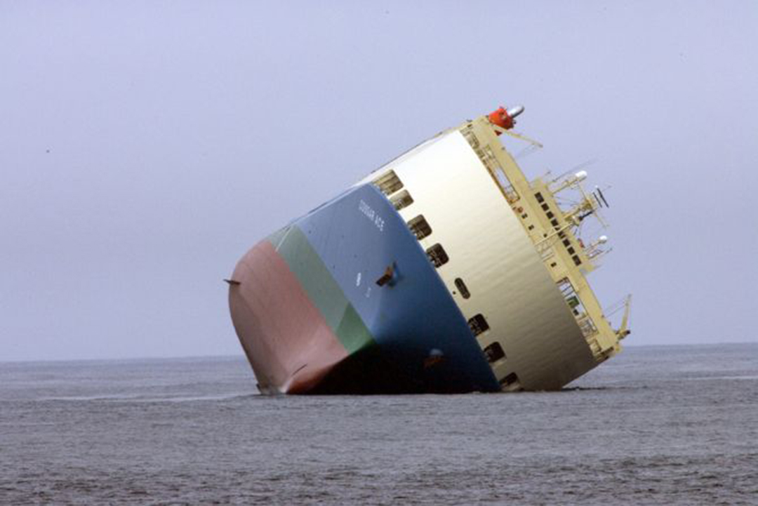


Figure 1: A heeled ship ( Courtesy: Googleimages)


However, invariably in all seas, the ships have to face the same problems of waves, environmental vagaries and sometimes interplay of both in worse case scenarios. Moreover, internal factors like improper distribution of loads, structural breach or sometimes problems in maneuvering and course-keeping can drastically alter the stability of the ship; i.e its tendency to remain upright! 

Stability of a ship has to be calculated for every situation a ship have to face, whether it is sailing in normal conditions or facing with storms or even on the jetty/port.  Calculations and tests are carried out both during design phase and after construction for estimating and improving the ship efficiency.


INTACT STABILITY


A ship when not damaged is said to possess intact stability. Stability deals essentially with the rotational motion of the ship viz., Roll(heel) and pitch(trim), former being the rotation around the X axis (ship's longitudinal axis) and latter for Y axis (ship's vertical axis).       


Figure 2


Take a Barge for illustration, Taking its Transverse section ( a plane along Y-Z axis ). Angle BMB’ = θ


 Figure 3


Let us assume it to heel by a small angle. Consequently, it's centre of buoyancy would change. However, it's centroid would remain same (assume no hanging weights and free liquids anywhere inside the ship). The line on which buoyant force acts is called line of action. Also the area of immersed and emerged wedges are equal. Now, as seen in the figure, Buoyant force and weight of the ship are making a couple acting in the opposite direction to the rolling motion. This will tend to undo the heel.

The points shown in the figure are very important. Point M (Metacentre point where the line of action meets the centreline of the ship), is most important, many of the calculations which are done deals with M.
The moment relation used for the righting arm (GZ) in the condition of heel is as follows:

                                                     GZ = sin θ*GM

where GM is the metacentric height measured from the Centre of Gravity and the Metacentre. 


GZ Curves and Calculations 


These curves are drawn With GZ on the Y axis and Heeling angle on X axis. If we see the general GZ curve, for small angles, righting lever GZ is proportional to heeling angle and thus a tangent can be drawn through origin which gives GM.
Till the maximum GZ value, there is a variation in the rate of growth of GZ value, the point where rate tends to decrease is point of contraflexure and the angle is angle of contraflexure. Now, above points are valid only when neglect many factors which contribute to ship instability.
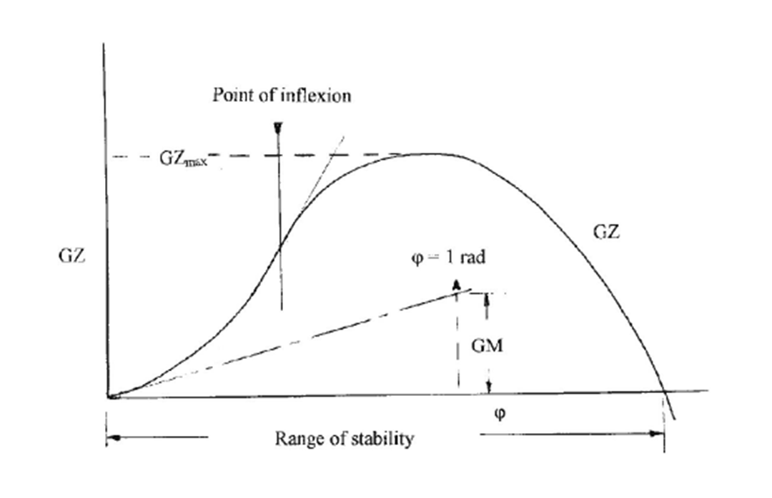

Figure 4: GZ Righting Curve of Stability ( Courtesy : Basic Ship Theory)


Area under the graph gives the energy stored.

This graph is of equal importance for both  naval architects and ship officers, while former draws this during design phase and latter every time before a voyage keeping in mind the path as well as the conditions they have to face (stability booklet is an important aspect in every voyage of a ship). 

In Submarines, the point M and B are coincident. Also for the stability G should be below B as opposite to any floatable.


FREE SURFACE EFFECT


This is a crucial problem pertaining to any stability factor of a vessel. As the ship heels, a pseudo force acts to any liquid which is present inside and thus the liquid changes its position thus changing the position of G, and we know with changing in G, values like GM, GZ would change and thus contribute to instability.


Figure 5: Wall Sided Ship with liquid contained in a wall-sided tank (Image Courtesy: Basic Ship Theory)


Due to change in position of G, GM of the ship would change according to the following
formula : GM (new)=GM (old) -K (I / Displacement)
Where K is relative Density of liquid with respect to seawater
And I is moment of inertia of liquid surface on plane.


The factor has to be subtracted from the graph and a corrected set of GZ curve is obtained.


Special measures are taken to reduce free surface effect such as Bulkhead Division, filling the tank to brim etc.

If the heeling angle increases, and GZ lever in not enough to counterbalance the
heeling force, ballasting water in opposite side can be done, though draft would increase, but it would undo the heal at the same time. 

The factor has to be subtracted from the graph and a corrected set of GZ curve is obtained.


Hanging weights can have same effects be changing centre of gravity of the ships.
When the ship is unloading cargo with a crane on board, and it is on the verge to unload it on jetty, ship starts to heel and as soon as it keeps it on the jetty, it oscillates until it achieves upright condition.

Reduction in GM can also be seen during rotational motion when an aircraft or helicopter lands or takes off from a ship or an automobile moves in a RORO vessel.
Sometimes there is a permanent angle of heel or trim which may be due to uneven
distribution of weight or due to negative GM, former being called Angle of List and latter Angle of Loll. 

Angle of Loll


Due to negative GM at zero heel angle, the ship heels until it's GM becomes positive. This continual unbalanced heeling act takes place in an oscillatory fashion. 

Figure 6: GZ Curve indicating Angle of Loll ( Courtesy: Wikipedia)

As shown in the figure, there is a negative GZ and consequently the tangent drawn also gives the negative GM. But as soon as the GZ starts to increase from 0, the tangent gives a positive GM.

 Now, if the ship heels further, same happens, but here the upright condition is not achieved, it would oppose the heel only till angle of loll. Angle of loll is due to external forces, it should not be confused with angle of list which is due to internal shift of moment forces.


Also at some considerable angle, the Deck starts to immerse, also knows as angle of deck immersion because it may be the maximum angle upto which rolling motion can be allowed because of open spaces at deck which may allow water to enter into the ship.

RORO vessel Cougar Ace ( IMO no. 9051375), which capsized in 2006 was reportedly being erroneously ballasted to undo its heel caused by a wave slap.  Though cause of the loss in stability is still not crystal clear,but speculations are that the ship had developed an angle of loll due to external force ( sea wave ) which would have caused the vehicles to displace and ultimately gaining an angle of list which heeled her further. Though she was
recovered and repaired. She is wall sided and have a large freeboard which then allowed her to prevent deck immersion. Deck immersion is a serious problem which can cause a ship to sink.

CROSS CURVES OF STABILITY 


Due to varying loading on ship, the centre of gravity keeps on changing. Also with loading or unloading, displacement changes. As the value of GZ curves changes with displacement of the ship, it is tedious to draw it for each displacement value. SZ curves makes the task much easier. If we take any arbitrary fixed point S the perpendicular distance SZ with respect to line of action, A set of following curves are obtained.

Figure 6: Stability Cross Curves ( Copyright: PNA) 
                             

From the curves as it is seen, at a particular displacement Value of SZ is found out for various angles of heel. These could be put into the following formula and GZ could easily be found out.


GZ = SZ + SGsinθ,
             SG=distance between the arbitrary point S and Centre of Gravity G. 


SZ curves only depends upon the geometry of the ship and hence can be drawn
during the design phase.

If we consider the case of an Aircraft carrier, it can have a good amount of flare so as to
perform well in rough waves, and its pitching motion have to be considered. These type of ships pitch and roll simultaneously so as to maintain stability. While if we take an large Cargo Carrier or a ship with tumblehome, the waterplane area is very large so there is very small pitching.


There much more criteria for stability with more formulas and concepts applied on different kind of ships to gain stability and control over the ships. However, we limit our discussion to the basic concepts without delving deeper. Stability is a big pastureland in oceans and our venture into a vessel's performance is incomplete without it. 

It is not just related to a set of mathematical interpretations but the physics behind it and its applicability in all types of ship operations is of pivotal character. We would come up with our next article related to the precise detailing of the practices carried out often in vessels to reduce risk of heeling due to free surface effects and careless loading-unloading operations.LSD

Article by: Kartik Garg and Kushagra Gupta 

Tuesday, 6 September 2016

Unconventional Offshore Structures-Wind Farms


Offshore Structures have been one of the most indigenous creations of man as it gave him access to the nature’s treasury of fuel and mineral reserves present in ample amounts underneath the oceans. A very important objective behind offshore structures is that man still has his limitations at land. Venturing into the oceans for the quest of abundant resources which were by far, unavailable or scanty in land can meet most of his needs.


Figure 1. Illustration of offshore extraction ( Courtesy: www.googleimages.com)


With various types, their research and development needs a lot of work force and statistical data. Different parts of ocean have different kind of weather and wave pattern to which an offshore structure is subjected. The external forces includes waves, wind, currents and corrosion along with other environmental vagaries.We know these structures are built at higher stakes and thus must reciprocate greater revenues which needs the efficiency to be maximum.


So far we had known of conventional ones like Jacket Platforms, Rigs, Drill ships, Spars, FPSOs, TLPs, Fixed or gravity based structures. These are segregated as: movable and immovable. Most of them are dedicated to more or less the same types of purpose: exploration, extraction, processing and/or transportation of petroleum and oil products derived from the deep sea reserves. A lot of analysis is done on them including strength calculations, advanced extraction techniques, software interpretations or safer installation-cum-maintenance goals.

Figure 2.: Conventional Oil Rig (Courtesy: www.offshoretechnology.com)

 
But have we ever wondered, can offshore structures be solely employed for the sake of exploiting resources that were limited or absent on land? Can they be utilized as improvements over infrastructure that are already present on land for better outcomes?


The answer lies in certain unconventional offshore structures such as wind farms, subsea pipelines, unconventional offshore gas stations or hydel-power installations which are focused mainly on tapping abundant 'oceanic' natural resources ( plentiful, renewable) for the purpose of generation of power on a widespread scale. As we are well aware of, renewable resources such as coal, natural gas and other earth derivatives are dwindling drastically. Thus to meet the insatiable needs of the ever-inflating population, Alternative forms of natural resources should be ingenuously exploited. Some of them are already materialized, but more needs to be done for achieving a global trend. 

Here we limit our discussion only to Offshore Wind Farms- a big trend setter . Later we take some of the others.

What are Offshore Wind Farms?


 Offshore Wind Farms are exemplary modern developments of tapping wind energy at seas for widespread harnessing of power as compared to landmass.


Figure 3: Offshore Wind Farm ( Copyright: www.tokyotimes.com)


Despite wind farms being relatively old technology on land, they have gained more credibility on seas in the recent years. Have you thought why?

The wind pattern on seas or vicinal to the shoreline is much more uniform, stronger and consistent as compared to that on land surface. Thus, this can be opportune in tapping wind energy on a much wider scale wielding more influence in generation of electrical power. According to a recent study by the United States Department of Energy, up to 50% of more power can be generated by an offshore wind installation than a land installation given the same turbine capacity. This is a boon actually for us! Given our vast ocean areas, if judiciously tapped, offshore wind farms can supplement a huge stake of our global energy demand.


The first offshore wind farm technology came up in Denmark in 1991. Since then, it is having a dramatic surge, especially in the Western frontiers. Till now about 4.5 GW of offshore wind installations are present worldwide, European countries being the maximum stakeholders and the Americas following close by. Around 30 GW is coming up and by 2020, an optimistic target of 75 GW is sighted. Major exploiters of them are Denmark, UK, Germany, US, Japan, China, South Korea, Belgium, Sweden, Portugal, Norway and Netherlands. India is also on the move with 100 MW planned along the Gujarat coast.


Requirements and Operation


Figure 4: Wind Farm (Copyright: www.theguardian.com)


Wind turbines convert the kinetic energy in the wind into mechanical power, which in turn generates electric power by induction. A generator can convert this mechanical power into electricity for commercial use. They are mostly designed for shallow waters, mostly continental shelf (preferably depths of 9-14 metres). Why?

  • Installation procedure is cheaper and easier  
  •    Moreover, building them on the continental shelf makes it relatively easier for drawing             transmission lines to the shore than from deep sea. 
  •   Maintenance can be done frequently and as and when required.
  •    Safeguard from adverse, unpredictable weather conditions deep sea.
  •   To avoid interference with the mid-ocean traffic. 

f     Now most of the offshore wind farms have a strong pile that is driven into the seabed. This  supports the nacelle and the tower. 


Figure 5: Nacelle of a Wind Farm installation (Courtesy :Wikipedia)


      The Nacelle is a shell adjoining the blades which houses the blade hub, rotor, generator, gearbox and the remaining electronic components.The Tower is the extension of the monopile and rises vertically above the waterline supporting the entire structure. The entire setup has a height of around 200 feet with additional 80-100 feet of piling foundations below the mud line. They are mostly three-bladed with the height of the farthest tip being up to 500 feet above seabed. Following image illustrates better.


Figure 6: (Courtesy: www.offshorewind.blz)


      The blades are similar to aircraft propeller blades (aerofoil sections) which are designed to turn in response to blowing air at a relevant speed and direction, which spin a drive shaft connected to a high-capacity generator producing electricity. Operational nameplate ratings of wind farms can vary from 2 to 5 MW (Find out about nameplate ratings).  

     After Production


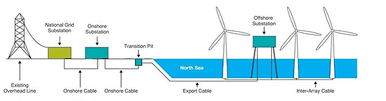
Once the power is harnessed, it has to be distributed to the shore substations for further use. This is the most cumbersome thing in case of wind farms as contrary to the oil platforms (where fuel could be stored or transported through ships or subsea pipelines). One essential feature is the use of Electric Service Platforms (ESPs), which act like intermediate ‘offshore substations’! They are placed in a region within the radius of vicinal substations, or reckoned as the turbine array.  The power output from the turbines is transmitted through high tension undersea cables to the ESPs. These either store or transmit the power to the grid at shore, from where it is distributed elsewhere. Underlaying of subsea pipelines is a critical task and has to be done with precision, high design reliability and safety factors.That’s the prime reason for keeping the wind farms as much closer to the shore as possible (as we had discussed before). 


Figure 7: Distribution layout of an offshore wind farm(Courtesy: googleimages)


Figure 8: An Electric Service Platform (Courtesy: www.boem.gov)


 A big problem with these offshore wind farms is that they are constantly exposed to the ocean environment. Thus their design criterion and basis for modification is different from that of onshore or land-based structures. Let’s see some of them:

  • Assessment of the structural design criterion is a very difficult task as the loads on the sea are highly large and unpredictable. Prediction of the dynamic loads such as wave, wind, current, pressure loads are analysed in details. The climatic patterns or the predominant wave actions under variant sea states are studied in detail before installation.     
  •  A site-based design is done for the particular installation as unlike land, the environmental condition in the waters are highly non-uniform. Thus design should always have a ‘fit’ to the location of operation. Water depth, topography of seabed, salinity, geology of the type of underwater soil and other miscellaneous geotechnical details are studied before laying out the design. 
  • The pile foundation has to be penetrating deep into the seafloor and strong enough to withstand the uncertain loads encountered in the sea. The effect of all the six degrees of motion in water (surge, sway, heave, yaw, roll, pitch) are taken into account as for any marine structure.
  •  As the weather in oceans is highly varied, specialized internal climate control systems are employed to maintain proper conditions congenial to the operation of the components.
  • Measures for stability of the towers and its resistance to waves, wind or icing accretions is done.
  • Corrosion is a pressing issue in oceans. Thus higher grade paints along with other modern anti-corrosion measures are applied on these.
  • As maintenance is not that easy every time, automated greasing and drainage system is inbuilt into them. Self-heating and cooling systems are also employed.
  • Problems of navigation are also sometimes grave. Thus, apart from selection of leaner marine traffic sites for installation, they are also specially equipment with emitters for navigational safety. 
  • A high degree of precision is used for supply of power through lines post-production to the land-shore.

Figure 9: Often wind farms are a big problem to ship traffic

 Advantages and Disadvantages


Like it is said, everything has its pros and cons. Though wind farms have emerged to be one of the most ideal applications of oceanic exploitation for mass productions, it is facing challenges. However, on judicious planning advantages outweigh them.

Advantages:

ü   Primary advantages of wind power are that it is free, renewable, clean, non-polluting source of energy. 

ü  Land acquisition problems are eliminated.

ü  Constant wind to enable greater productivity.

ü  Facilitates port and harbour infrastructure. Also acts as the primary source of electricity in remote coastal villages.

     Disadvantages:
  •   Ecological problems to marine underwater life.
  •  Proximity of seabirds to get struck by.
  •  Very high initial investment
  •  Navigation  problems
  •  Tedious job of laying high-voltage underwater wires over long distances to the shore.
  •   Problems of fishing and trawling
  •   High noise and vibration created by installation and operations.
  •   Prone to damage by lightning or very adverse sea states 

     
      The potential of offshore wind is enormous. It could meet Europe's energy demand seven times over and United States energy demand four times over. In India too, it can supplement the shortfall power over a large number of regions, especially rural areas and large cities at the same time, where excess consumption often leads to crisis. Offshore wind power generating stations have a few advantages over the onshore ones like wind blows at a higher speed as we move far away from the shore so more power can be generated from few turbines. Most of the world's largest cities are located near a coastline avoiding the need of long transmission lines and constructing an offshore wind farm makes sense in a densely populated coastal region with high property value.


Figure 10: Some of the global statistics ( Courtesy: www.gwec.net)


      Presently only 3% of global installed capacity is offshore. Relatively high costs remains the biggest challenge for offshore wind development. But forgoing its problems and making it instrumental to meet the quantum of our short falling energy reserves. Also as we know, time is money. Thus, improper and slack utilization from the early stages can make any asset a liability.LSD

        
     Article by:   Kartik Garg


Friday, 25 March 2016

Dynamic Amplification and Extrapolation of Fundamental Laws


Study of the unpredictability of wave based phenomenon is of great importance in seakeeping.


We are accustomed to apply Newton’s Equations every now and then. But how much do we know its validity? If we seek the answer to this question, even the masterminds have to rack their brains! It is a universal and harsh truth that these are applicable to only a meager number of bodies around us.

Coming to the context of ships, Newton’s ‘linear’ postulates falter in front of the large diabolical forces and unpredictable rapidly-varying disturbances, it is subject to. If we take the pain to estimate the forces over a stipulated span of time on a side shell plating of the outer hull, we could notice that neither the strength, intensity, distribution nor the fetch of the generated stress can be estimated by our conventional methods. Dramatically enough, every single physical parameters associated with the region wields as an abrupt time-varying function. For example, the stress distribution would be following abrupt frequency response changes of intensity. This is where we introduce a non-dimensional parameter known as the Dynamic Amplification Factor. Mathematically, it can be expressed as the ratio of the maximum permissible load, Um to the static load applied to the same body, Us. Or in other words, it takes into account the “static-equivalent load” under the same conditions.


Rarely, in ships do we find static loads acting. The loading like that of storms, rain, earthquakes, floods or calmer ones like live traffic loads on a bridge, the loads encountered by a ship under all abrupt sea states are essentially highly accelerated and variant, viz. Dynamic loads. Have you ever wondered at the rogue deep sea waves lashing out at a ship? Do you think that the aggregate stresses embarked upon the ship at its multitude of structural locations could be simply assessed by a petty Newtonian Load equation? The answer is a big no. A lot of tedious work has to done by designers/naval architects, engineers, seafarers to analyse the nature of the loading at all strategic locations of any structure to execute its probabilistic failure computations.


The most preliminary application of Dynamic Amplification Factor on a ship would be to study the forces enacting on a single isolated object on board while a ship hurls above a big sea wave. This situation is analogous to the case of a simple elevator! We know that whenever an elevator goes upward with a certain acceleration, weight experienced by an object in it increases. Similarly, when a ship is aloft a wave, any object on board experiences an “added pseudo force”. 

Hence, the classical equation, F=mg gets modified in the form of

 F= m*g*(DYNAMIC AMPLIFICATION FACTOR)

The basic concept lies in the fact that when a body is subject to dynamic force, its effects are more pronounced due to the materials inability to promptly react to the sudden disturbance. This is where the induction of the DAF equalizes the effects of static and dynamic loading under the given conditions. 

The determination of the Dynamic Amplification Factor, however is a cumbersome task where it involves a compact knowledge of the nature of the frequency response curves.


Some of the methods involved are complicated and require high levels of expertise. Averaging of the stress variations from time-to-time in a system like that of a ship to deduce the DAF is a challenge to a naval architect. The designer/builder hones his skills again in turn to implement this in the detailed structural design and material analysis. Thus this simple ‘extrapolation’ of the fundamental laws have pronounced implications in the ship structure analysis.

By: Subhodeep Ghosh (Originally posted on our page)