Sunday, 23 March 2014

EEDI - The Future of Green Shipping

Environmental issues have always been an integral part of the global shipping industry. Starting with greenhouse gas, ballast water, oil pollution and much more. In fact, it was estimated by International Maritime Organization (IMO) that there might be an increase up to 72% in carbon dioxide emissions from shipping if no actions are taken. Therefore, numerous meetings, conferences and discussions at IMO have resulted in the development of an energy efficiency design index (EEDI) that has the broad and emphatic support of Governments, industry associations and organizations representing civil society interests. The main stakeholders over whom the regulation will have a direct impact over are the shipowners and operators. 


What is the EEDI ?
EEDI is an index quantifying the amount of carbon dioxide that a ship emits in relation to the goods transported. The actual EEDI of a vessel is called the "attained EEDI" and is calculated based on guidelines published by IMO. The result must be below the limit ("required EEDI") prescribed in MARPOL.

For existing vessels, the EEDI is in most cases irrelevant. For new ships, a technical file must be created showing the attained EEDI and its calculation process. The EEDI and the technical file will be subject to verification by the flag administration. Note that the EEDI and the Technical file are not required for all types of ship.

The EEDI for new ships is the most important technical measure and it aims at promoting the use of more energy efficient (less polluting) equipment and engines. The EEDI requires a minimum energy efficiency level per capacity mile for different ship type and size segments. It was implemented since 1 January 2013 for a first two year phase zero when new design meets new reference level for their ship type, the level is to be tightened every five years and so EEDI is expected to stimulate continued innovation. 

As long as the required energy efficiency level is attained, ship designers and builders are free to use the most cost efficient solutions for the ship to comply with the regulations.

The CO2  reduction level (grams of CO2 tonne mile) for the first phase is set to 10% and will be tightened every five years. Reduction rates have been established until the period 2025 - 2030 when a 30% reduction is mandated for applicable ship types calculated from a reference line representing the average efficiency of ship built from 2000 and 2010.


The empirical formula of EEDI is as follows:

EEDI = (Power · Specific Consumption · Carbon Conversion) / (Capacity · Speed)

However, EEDI as presently drafted is not applicable for all ships, especially non cargo carriers and also not for all types of propulsion system (eg. ships with diesel-electric, turbine or hybrid propulsion systems will need additional correction factors).

The first iteration of the EEDI has been developed for the largest and most energy intensive segments of the world merchant fleet, thus embracing 72% of emissions from new ships and covering the following ship types: oil and gas tankers, bulk carriers, general cargo ships, refrigerated cargo carriers and container ships.

You might think that why RO-RO is excluded even if they carry cargo but if you carefully analyse the formula given above you would find that the design of fast ships like RO-RO will never present a good index as speed is taken too linearly into consideration here and hence vessels with Diesel electric hybrid system propelled vessels are difficult to be included in the formula.

The EEDI requirements will apply to new ships above 400 gross metric tons only, where "new ship" means a ship:
  • for which the building contract is placed on or after 1 January 2013.
  • in the absence of building contract, the keel of which is laid or which is at a similar stage of construction on or after 1 January 2013.
  • the delivery of which is on or after 1 January 2015.
A ships attained EEDI must be equal to or less than the required EEDI of the ship type and size, which will be a function of the reference line value and a reduction factor X,


Reference lines have been developed by the IMO for a number of ship types. The EEDI reference lines refer to statistically average EEDI curves derived from data of existing ships. The reference lines are ship specific and dependent on ship type and size. Reference line values are calculated using the following table and equation: 

Parameters for determination of reference values for different ship types (MARPOL Annex VI, Regulation 21)


Reduction factors will be used to implement the EEDI in phase so as to gradually reduce the Required EEDI in much same way as NOx and SOx limits. These reduction factors will apply to specific ship types and sizes. The following figure shows how the reduction factors will be implemented over time. 
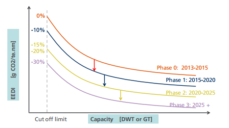


The following table gives a more clear idea of the reduction factor as per ship types & sizes: 
Reduction factors(X) for Required EEDI versus Attained EEDI (MARPOL Annex VI, Regulation 21)

In addition there are a series of correction factors that moderate the equation. These account for:

  • Ship Design factors (e.g. Ice-Class and Shuttle Tankers)
  • Weather factor for decrease in speed in representative conditions
  • Voluntary structural enhancement
  • Ships built to Common Structural Rules (CSR) 
  • capacity correction for chemical tankers and LNG ships


What is SEEMP ?
SEEMP stands for Ship Energy Efficiency Management Plan. The main purpose of the SEEMP is to lay down a mechanism for the company or ship to improve the energy efficiency of a ship's operation and preferably link it to a broader corporate energy management policy. All ships must have a SEEMP on board before the issuance of the first IEEC (International Energy Efficiency Certificate).


The SEEMP will initiate monitoring and target setting and look at concrete measures to be implemented for each vessel.


List of parameters that effect the EEDI

The following are provided as a list of typical parameters which may have an effect on ship's EEDI. Note: This is not an exhaustive list.

  • Ship type and design for ice
  • Type of fuel
  • Size and Specific fuel consumption of main engines( or main propulsion motors)
  • Specific fuel consumption of Auxiliary (power generation) engines
  • Hull Form
  • Hull appendices
  • propeller
  • Electric power requirement for non-propulsion systems
  • Capacity at Summer load line
  • Draft and trim at Summer load line
  • Energy saving devices as specified in EEDI Technical file


Conclusion
Following adoption in 2011 and entry into force in 2013, the EEDI will aim at reduction of about 45 to 50 million tonnes of CO2 emissions from all new ships by 2020. For 2030 the reduction will be between 180 - 240 million tonnes annually.

There is therefore, every confidence, among the vast majority of the international maritime community, that the EEDI will result in more efficient ships, in reduced emissions of GHG's, in Environmental effectiveness and in a significant contribution by a global industry to the global efforts to stem climate change. LSD


Article By: Tanumoy Sinha


Author's Note: The article 'EEDI - The Future of Green Shipping' focuses on the importance of Energy Efficiency & Green shipping, and how EEDI can be used as a tool to achieve that goal. I have written this article based on my experience and technical knowledge on the same as a Naval Architect. The picture used above does not belong to LSD, and full credit for the same goes to their respective owners. If you have any queries or doubts, write to me at learnshipdesign@gmail.com


Risk - Based Ship Design (Part One)


In one of my previous articles, I wrote on how innovative the maritime industry is. Getting a step deeper into discussing the design methodologies used in the industry to maintain the levels of safety at par with innovation, this series is on "Risk - Based Ship Design" - A design methodology which treats Safety as an Objective and not a Constraint.

I felt it would be better to get along with the fundamentals of this design methodology, before actually getting into the intricacies (which will be dealt with in the further parts of this series). I tried my best to make the introduction as easy and interactive as possible, through the prezi below. 

It is reccommended to view the presentation in fullscreen mode. Please wait for the prezi to load before viewing it. You can either manually advance the slides or set it on automatic transition for least efforts.


LSD


Article By: Soumya Chakraborty


Author's Note: The next parts of this series shall be based on design considerations and methodologies used in Risk - Based Ship Design. Thank You for reading. In case of any doubts or feedbacks please comment or write to learnshipdesign@gmail.comlearnshipdesign@gmail.com

Friday, 7 March 2014

Know A Ship - RoRo Ships- Part Two

RECAP:


Last time we spoke about RoRo Vessels in the first article. A reading of the article gives some idea about the history and utility of the these vessels.This article will focus on the ship from a designer's perspective.


THE DESIGN:


The main requirements against which a design is to be developed will generally include certain statements.


  • Passenger Market for which it is intended to cater- deluxe,middle market or the popular "Package Tours".
  • Passenger Numbers which will determine accommodation and cabin types.The number of vehicles and the mixture of their types should be incorporated into their design.
  • Normal service speeds and maximum service speeds in different legs of cruises.
  • Sea areas of interest and times of the year.
  • Maximum Duration of cruises between restoring and refueling at ports.
  • Details of loading and unloading ramps at each of the ports the ship is intended to use.Particulars of the ramp,distance to center of the ramp from side which ship will be berthed against.
The dimensions are largely determined by the vehicle deck(s) layout.Large vehicles heavily influence the design.The ramp is divided into lanes,usually two or more.The length determines the positioning of engine casing and access stairs.In less maneuverable vehicles,the bow to stern door straight run is preferred. This keeps the weight differences between lanes minimized and the hoist-able car decks can be easily arranged in the position.

With  the ship's length known, the beam of the ship can be determined by calculating the multiples of vehicle widths and access space.Now, deck capacities are estimated using data on how cars and heavy vehicles should be arranged.The tween deck height favors heavy vehicles and the ship sides are suited for cars.When further optimization is required,the cars are run down ramps to lower or up to higher decks as required


Bow Ramp Mechanism on a Ro-Ro Ship


Layout of a Ro-Ro Vessel
.


The tween deck space is suited for larger vehicle cargo


Now the berthing requirements are examined and modified if required to suit the ship design.

Ship weight calculations are carried out and suitable block co-efficients  and drafts are determined.
These days owing to some previous tragedies.(Read Estonia and See Herald of Free Enterprise), certain Ro-Ro exclusive safety regulations are now factored too.
  • Increase free-board to car deck to check heavy inflow of water into this deck.
  • Providing heads that ensure that water drains away through drains/scuppers.
  • Sometimes,inflatable air bags at ship sides are also considered. 
With the depth to car deck fixed the design can now be developed as required considering the machinery weight,power estimates with decision on type of machinery with diesel,diesel-electric and gas turbine electric being main contenders. 

Spacing and number of water-tight bulkheads are decided upon. Positioning of public rooms are done and accommodation of crew and officers are allocated respectively based on the frame spacing.Preliminary stability assessment is done using established methods. Now the shipbuilding process proceeds to the next stage i.e. ship calculations.


Lift-on/Lift-off (LO/LO) Ships:
LoLo vessels (acronym for Lift on - Lift Off) are vessels that can transport a range of different products as a result of their flexible cargo space,high container capacity and on board crane facility. Lift-on/Lift-off (lo/lo) cargo is generally containerized cargo that must be lifted on and off vessels and other vehicles using handling equipment.
A LoLo operation is when cargo is loaded and discharged over the top of the vessel using cranes or derricks. LoLo vessels can load and unload cargo at Roll On-Roll Off (Ro-Ro) ports, Load On-Load Off (Lo-Lo) ports and at unserviced jetties, using its own cranes.
 At-sea demonstration of their Large Vessel Interface
 Lift-on/Lift-off (LVI Lo/Lo) crane system.


Cargo vessels can be equipped with a variety of cargo handling systems the most commonly encountered systems being classified as either lo-lo or ro-ro (the vessels may sometimes be referred to as lo-lo or ro-ro vessels even though it is possible to have both loading capabilities on the same vessel). 
Each vessel type and cargo handling system has applications that may be more appropriate for certain specific commodities and cargo. In addition, each has it's own advantages and disadvantages in terms of cost and service characteristics. Matching the technology to available port infrastructure, commodity markets, and labor constraints will have a strong influence on the economics of a particular operation. LSD 


Article By: Sudripto Khasnabis


Author's Note: This article is the second one about Roll-on/Roll-off  Vessels.The next article will talk about vessels with standardized cargo dimensions-The Container Ships.The section shall proceed regularly with similar articles about other ship types with a common aim of making the reader aware of the general principles on which their design and construction is based and their utility and characteristics. The videos and the figure do not belong to LSD, and full credit for the same goes to their respective owners. If you have any queries or doubts,do not forget to write to me at learnshipdesign@gmail.com

DP System on Drillship CHIKYU: Dynamic Positioning System- Part Two

FLASHBACK


This article is the second part on the series of "Dynamic Positioning System". The first part of this series had focused on an introduction to DP Systems and their application in pipe-laying and cruise ships. The second part is a case study on the DP System on Drillship CHIKYU.


PURPOSE OF DP SYSTEM ON DRILLSHIPS


A drillship requires to maintain her station or heading during underwater drilling operations. The dynamic effect of waves, wind and underwater currents take huge toll on the safety of the operation of the vessel. The drill and riser pipes are nothing but like strands of thread when they go down to depths of the order of 2 to 3 kilometers below the sea level. Any significant disturbance in the orientation of these structures due to the ship's uncontrolled motions during drilling operations have every possibility to trigger a major maritime disaster. 

The Dynamic Positioning System ensures that the ship maintains her station or a pre-defined heading. Drillship CHIKYU is Japan's scientific drilling vessel designed for drilling operations up to depths of 7 kilometers. This article is a case study on the design of DP system used on-board the ship.


DESIGN OF CHIKYU'S DP SYSTEM

MAIN PARTICULARS:


Main Particulars of Drillship CHIKYU (Info-graphic)


DP SYSTEM DESIGN PROCEDURE


The design process of the DP system of the ship included results from tank tests and a combination of static and dynamic simulation of the model using its thrusters, generators, and position keeping ability. So the basic control flow of the system was generated (refer the flowchart below).


The forces which control the motion of the vessel can be categorized as:


  • Feed forward forces: The forces of waves, currents and wind, which are basically the external forces acting on the system, initiating deviation. They were estimated using the Kalman Filtering Technique (refer to the link for the calculations based on Kalman Filtering Technique)
  • Feed back forces: These include the forces required to be generated by the thrusters in order to compensate the feed forward ones, to minimize deviation or maintain required heading. 
Consequently, there is a constant monitor on the electric load on the power system, according to the number of thrusters, the azimuth angle and RPM of the thrusters required to maintaining station.


POSITION REFERENCE SYSTEM:

In order to maintain station or predefined heading, the DP system takes help from a series of position reference systems used on board the ship. These systems constantly feed the ship's position to the DP sensors on-board the ship. Each position reference system in use, has its own set of advantages and disadvantages. Therefore, a ship using DP system, makes use of multiple position reference systems to maintain redundancy and accuracy.


The ones used on-board Drillship CHIKYU are:


  • Network DGPS:  In a Network Differential Global Positioning System, the vessel obtains its co-ordinates in terms of latitudes and longitudes with reference to the World Geodetic System. It uses a network of multiple satellites (CHIKYU uses INMARSAT satellites) and land reference stations called 'links'. The choice of links depends on the operational area of the ship. 

Layout of DGPS Configuration

  • GPS-GLONASS System: The Global Navigation Satellite system is the Russian powered counterpart of USA's GPS system. The advantage in using a GLONASS system is that, the GLONASS satellites have higher inclination (upto 65 degree latitudes) as compared to GPS satellites which have maximum inclination of 55 degree latitudes. This enables better connection availability even in higher latitudes. A GPS-GLONASS System therefore uses the feeds from both, GPS and GLONASS reference systems for position reference. 
  • HAPRS (Hydro Acoustic Position Reference System): HARPS applies the theory of acoustic underwater ranging by communication at hydroacoustic frequencies between hull mountd transducers and sea-bed located transponders. 


CONFIGURATION OF THRUSTERS:

CHIKYU uses a combination of thrusters for its dynamic positioning. The layout of the azimuth thrusters and a side thruster under CHIKYU's hull can be clearly understood in the following graphic representation. 

Layout of thrusters in Drillship CHIKYU


DP CONTROLLING FUNCTIONS:

Based on different sea conditions and operational requirements, the dynamic positioning system on Drillship CHIKYU is set to various modes of operation, each having a specific characteristic and purpose:

A) DP Mode: 

  • All thrusters controlled automatically to maintain station keeping or to keep the vessel's motion steady depending on the external forces on the ship.
  • If the target position is altered, the ship will move towards the target with steady speed maintaining controlled deviations from its defined path. The steady speed can vary from 0.1 knots to 0.5 knots.
  • Even for adverse sea conditions like 2.5 knots currents (upto 30 degrees against heading angle), 23 knots wind (upto 30 degrees against heading angle) and 5.5 m waves (upto 30 degrees from heading angle), the vessel can be safely operated in DP mode by increasing the control gain of the DP system. 
  • In calm sea conditions, the vessel's position can be fixed by automatically adjusting the azimuth angles. This is also called "Azimuth Fixed Mode".
B) AUTO HEAD Mode:

  • Vessel's target point can be set, and vessel moves steadily towards the target even in rough sea conditions.
  • The instantaneous direction of the vessel's heading can be controlled using joysticks on the DP control panel.
C) JOY Mode:

  • Vessel's heading and direction can be controlled using joystick on the DP control panel.
  • The thrust can be increased upto four times normal, using thrust power up button on the joystick itself.
D) NAVIGATION Mode:

  • While positioning the vessel on its drilling site, this mode enables auto piloting and navigating operations for precise positioning.
E) RACS Mode:

  • After the riser pipes are lowered, it is necessary to control the riser angle with respect to the vessel.
  • This mode enables the positioning of the ship with respect to the top and lower riser angle feeds from the DP sensors.
  • Thus, the riser angle always remains minimised during its drilling operations, irrespective of the sea conditions.


Concept Layout of RACS Mode operation


F) CONSEQUENCE ANALYSIS:


  • During operation of the DP system, it also analyses its position keeping capability.
  • In case the present hading or position keping falls below a preset value, the system automatically triggers an "Insufficient Thrust" warning to the operators.
  • This adds an additional layer of redundancy to the entire system.


RELIABILITY:


After the DP system was installed on the ship in 2004, numerous sea trials have been carried out ever since to maintain a check on the reliability of the system. Its position keeping ability has remained outstanding, and it has not shown a standard deviation of more than 5 meters even in the roughest sea conditions till date. LSD


Article By: Soumya Chakraborty


Author's Note: The case study on the DPS on drillship CHIKYU has ben carried out based on the tank test and sea trial results published by the concerned organizations. Flowcharts and pictures in this article do not belong to LSD. Full credit goes to their respective owners. Thank You for reading. If you have any doubts and queries, please comment or write to me at learnshipdesign@gmail.com


Monday, 3 March 2014

What's with the Bulb? - Part Three

If you are a beginner, read the first and second part of this series.

Design of a bulb is one of the most challenging works for a Naval Architect. A major portion of the economy is dependent on the design of the bow. The better design would lead to better efficiency and lesser fuel consumption. Hence, it is very important to know and understand every concept of the bulb design. However, in the following article we will be going through an overview of the major components required for the design, following which we shall go through the advantages and disadvantages of using the bulbous bow.

Mostly the design and shape of the bulbous bow is determined by model testing. However, on the basis of the design used till date, three major shapes have been identified.

TYPES OF BULB SECTIONS:

The various types of bulbous bow are as follows - 
  • Δ- type: The figure below shows the drop-shaped sectional area ABT of the delta-type with the center of area in the lower-half part. This shape indicates a concentration of the bulb volume near the base. The Taylor bulb and the pear-shaped bulbs belong to this type.
  • O- type: The figure below shows an oval sectional area ABT and a center of area in the middle with a central volumetric concentration. All the circular, elliptical, and lens- shaped bulbs as well as the cylindrical bulbs belong to this type.
  • ∇- type: The nabla-type also has a drop-shaped sectional area  ABT , but its center of area is situated in the upper-half part, indicating a volume concentration near the free surface, because of its favorable sea-keeping properties, this type is the common type of bulb. 

INTEGRATION OF THE HULL:
Depending on the shape of the bulb in comparison with the hull shape, bulbs can be divide into two types-

  • Addition Bulbs: The bulb shape is completely independent from the hull shape. Typically there is a knuckle resulting from the intersection of the bulb and the hull.
  • Implicit Bulbs: Sectional area curve is changed, part of the volume of the bulb is distributed aft of the FWD perpendicular. No knuckles are required.
In the bulbous bow by changing the entrance angle of the waterlines and the volume distribution, represents an effective mean of reducing the wave resistance. Some authors limit the usefulness of the bulb to the interval: 0.238<Fn<0.563. 

Bulb shape must be adjusted to the design conditions. Generally, at low speeds the effect of the bulb is negative. When the Fn increases, its effect becomes positive and increases up to a maximum value. From this point upwards, when the Fn tends to the infinity, the effect of the bulb tends to zero.


INFLUENCE OF THE BULB ON THE PROPERTIES OF THE SHIP:

Before discussing the influence of the bulbous bow on the ship resistance and required power, respectively, we should mention other important hydrodynamic qualities which play a role in the decision whether a bulb should be used or not. The change of resistance influences the thrust loading of the propeller and consequently, other propulsive characteristics of the ship like the wake and the thrust deduction factor.

The figure shown below(left) gives us the indirect influence of the bulbous bow on thrust deduction fraction. Both are increased by an additive as well as by implicit bulb, if the bulb ship has a lower total resistance than the bulbless form.


Advantages of bulbous bow:

  • Reduces the bow wave, due to the wave generated by the bulb itself, making the ship more efficient in terms of energy.
  • Increases the ships waterline length, slightly increasing the ship speed, reducing the installed power requirements and so the fuel oil consumption.
  • Works as a robust bumper in the event of collision.
  • Allows the installation of the bow thrusters at a foremost position, making it more efficient.
  • Allows a larger reserve of flotation or a larger ballast capacity forward.
  • Reduces pitch movement.
Strictly speaking there is hardly any disadvantage of using a bulbous bow, however a few factors must be always kept in mind before installing one, that is a bulb is only useful for long voyage ships, especially, Merchant Vessels. It operates only for a given range of speed, hence ships like Coastal Research Vessels, or for coastal fishing vessels it may be useless. Generally displacement ships whose froude number is less than 0.36 may find it advantageous. 

Aspects of Initial Bulb Design:


The bulb shall never emerge completely. The point at the forward extremity shall be at the level of the waterline.

Distribution of the bulb volume
  • Too much immersion does not produce any effect.
  •  Volume concentrated longitudinally near the free surface increases the effect of interference in waves.

The waterlines at the bulb extremity should have a thin shape but not circular, to avoid the flow separation.The bulb is advantageous in ice navigation – the ice blocks slide along the bulb with their “wet” side, which has a lower friction coefficient.

Computation Fluid Dynamics of the bulbous bow is very much necessary if you have to know the distribution of the hydrostatic pressure and the flow lines of the waves around the hull due to the bulbous bow.

Based on the experience, the designer must evaluate if:
  • The length of the bulb is adequate to the considered speed.
  • The over pressure generated at the sides of the bulb is adequate.
  • The bow flare does not increase too much the height of the wave at the bulb.


The bulbs shall be designed for the operational profile of the ship and not only to the full load condition. The bulb that reduces the most fuel needed for the required operational profile shall be the one selected.

Note the flow around the bulbous bow in the video below- 


Images of different types of bulbs in Merchant Ships:


LSD


Article By: Tanumoy Sinha

Author's Note: This is the third and last part of the series on bulbous bows. If you haven't gone through the first and second parts, please click on the respective words on this line. This article is the Third and the final part of the topic 'What's with the Bulb?'. It expounds to us about the various design aspects, CFD requirement and advantages & Disadvantages of the Bulbous Bow. I have written this article based on my experience and technical knowledge on the same as a Naval Architect. The picture and the video used above does not belong to LSD, and full credit for the same goes to their respective owners. If you have any queries or doubts, write to me at learnshipdesign@gmail.com