Monday, 3 September 2018

Cavitation - The constraining factor

Transportation across the oceans has attracted the attention of mankind since the dawn of history. What started with a simple bundle of logs has evolved into a huge sophisticated vessel of today. Earlier, wind (sails) and human power (by oars) were the only means of propulsion but since the advent of 19th century Mechanical Propulsion began to be used in ships. Most of the modern ships have quite similar propulsion arrangements consisting of a wheel rotating about a transverse axis with radial blades or paddles to impart astern momentum to the water around, giving it forward thrust . 


As the size of vessels grew, the thrust required from these screw propellers also increased. Consequently, the rpm of these propellers escalated. When the  propellers’ diameter is restricted and they are required to produce very large thrusts at high rpm’s  the propellers are likely to experience a phenomenon called “Cavitation”.

Cause 

Water begins to vaporise when its vapour pressure equalises the saturation vapour pressure. The vapour pressure of water is 1.704 kN/m^2 at 15 °celsius and 101.325 kN/m^2 (atmospheric pressure) at 100 °celsius. If the pressure inside water falls to the vapour pressure the water at that point begins to vaporise forming voids filled with water vapour. The formation of such vapour filled cavities is termed as cavitation.Cavitation also depends upon the purity of water. The impurities in sea water such as suspended solid particles and dissolved gases act as nuclei for the formation of cavities.Vapour cavities are formed locally but when pressure increases clear of this region the vapour cavities collapse or “implode”. This implosion occurs with a high impact force with stresses nearing 2800 N/mm^2. 


A propeller generates thrust by creating a pressure difference between the face and back of its blades. The pressure on the back of the blade falls below the ambient pressure and the pressure on the face rises above it. Hence, the back face of the blade becomes prone to cavitation.


Types of Propeller Cavitation

The type of cavitation occurring has two bases for classification :

   1.Classification on the basis of the region where cavitation occurs:
  • Tip Cavitation
  • Root Cavitation
  • Boss or Hub Cavitation
  • Leading Edge Cavitation
  • Trailing Edge Cavitation
  • Face Cavitation
  • Back Cavitation
    2.Classification on the basis of the nature of the cavities or appearance:
  • Sheet cavitation
  • Spot cavitation
  • Streak cavitation
  • Cloud cavitation
  • Bubble cavitation
  • Vortex cavitation
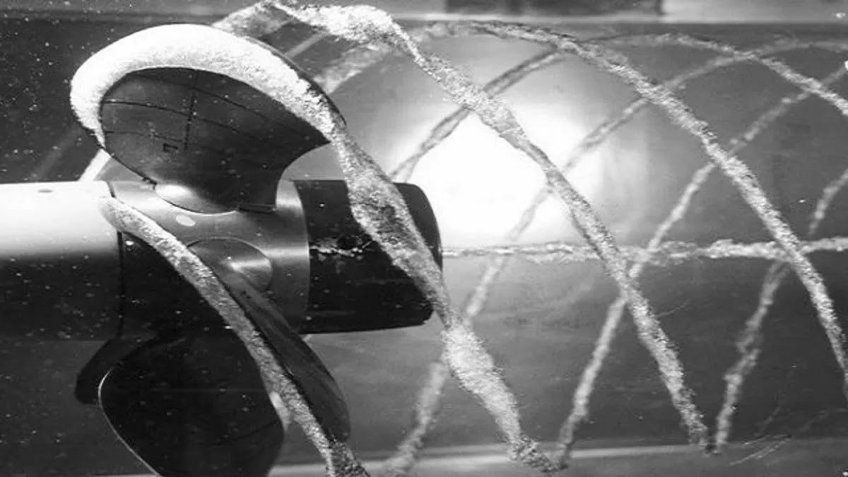
Cavitation exhibited in a cavitation tunnel in a stroboscopic arrangement
Hub Vortex Cavitation
Leading  Edge Cavitation
Tip Vortex Cavitation

Effects 


  1. Cavitation in marine propellers results in the increase of blade rpm without any appreciable increase in speed of the ship hence reducing the efficiency and thrust of the propeller. 
  2. When the bubbles implode they generate very strong local shock waves in water which generate a lot of noise and do mechanical erosion of the blades in form of pitting. The frequency of collapsing is generally around 15,000 Hz to 20,000 Hz. The collision intensity depends upon a number of factors-: 
  • Life span of cavitating bubble which is about three milliseconds which makes the event rapid. The faster the surrounding water collides, the greater the energy it possesses.
  • The size of the cavitating vapour bubble. Generally, the vapour bubble formed by cavitation at 68° Fahrenheit is about 35 times larger than the one produced at 212° Fahrenheit. A larger bubble corresponds to a greater amount of water colliding.
  • The quickness and amount of water together represent the total kinetic energy with which the imploding bubble attacks the metal.
  • It also accelerates corrosion in blades due to ‘Cavitation stain’. Cavitation Stain is a phenomenon where the oxidised layer that protects the metal is removed by cavitating bubbles hence making the metal vulnerable to corrosion. Corrosion damage is visually detectable and can eventually destroy the propeller.  
  • In the given figure a series of 18 shots show progressive events of flattening of a spherical bubble and finally imploding with the release of enormous energy.
Series of 18 shots show progressive events of cavitation

Pitting Due to Cavitation
Propeller Pitting due to cavitation

Prevention of Cavitation

Due to the detrimental effects of cavitation propellers are designed so as to restrict its level to a value so that its effects are negligible. It is achieved by following three methods:

  • Increasing the cavitation number.
  • Decreasing the loading on the propeller
  • Designing the propeller for uniform loading according to Keller criteria, which is related to the number of blades of the propeller, diameter, thrust, and the depth of shaft.

Supercavitation and Supercavitating Propellers


Generally it has been observed that it is difficult to avoid cavitation completely in high speed crafts where the propeller rpm crosses 1000 rpm. So instead of avoiding it some propellers are being designed such that they use this property to create a sheet of vapour around the propeller blades which increases the effective diameter of the propeller and thereby increases the thrust as well as the efficiency of the propeller. Cavitation is not a problem for these propellers as they are designed to work in cavitating zone. Although before achieving the design speed (when cavitation occurs) these types of propellers demonstrate very low efficiency due to their non-streamlined (wedge shaped) sections.

Super cavitating propeller with wedge shaped training edges


Supercavitation is even used for torpedoes and other high speed objects in marine environment. The vapour sheet formed due to cavitation corresponding to the high speed of torpedo encompasses the object thereby greatly reducing the drag and hence enabling higher speeds. They are being developed by defence forces in fast supercavitating torpedoes and war projectiles. For instance, the soviet torpedo named VA-111 Shkval, German torpedo Barracuda, weapons like SPP-1 underwater pistol, APS amphibious rifle.


VA-111 Shkval using the phenomenon of cavitation


Thus cavitation though has some serious detrimental effects, it can be used as a beneficial tool in particular cases. It is one of the most important factors determining the diameter and rpm of the propeller blade by placing major constraints. An optimum design and balance needs to be maintained between the blade diameter and rpm to obviate the risk of cavitation.


Article By - Soumya Sameer


Tuesday, 17 April 2018

Types of Propellers

Introduction

A propeller is a fan like rotating structure generally at the aft of a ship imparting thrust to propel the ship. Most ships use the conventional screw propeller. But in some ships depending upon the need and requirement, different types of propellers are used.

The different types of propellers with varying characteristics are listed below.

Paddle Wheel

Image Courtesy- Google Images.


 It is a very simple type of propulsion system. It consists of wheels with paddles attached at its periphery. It has its axis of rotation about the transverse direction of the ship above the waterline. The paddles get immersed in water only when they are at the bottom of the wheel. As the paddles rotate in water, they accelerate it, experiencing a reactive thrust from the water which is transmitted to the ship.
 It is of two types


  • FIXED: These are simple and easy to construct. In this type, the paddles are firmly attached to the wheel. This system requires wheels of large diameter so that they can enter the water at large angles. Large diameter means low rpm and more weight. This is the main drawback of this system.


  • FEATHERING: In this system, the paddles are attached at the ends of the wheel in such a manner that the angle of entrance is much larger than that of fixed type.By this principle, the diameter of the wheel can be reduced.

Tandem propeller

Image Courtesy- Google Images.


In this arrangement, two propellers are mounted on a single shaft turning in the same direction. Tandem propellers are fixed so as to reduce loading on a single propeller as it can lead to cavitation. Here the thrust is divided between the two propellers.
In normal loading, they are not of much use but in heavy loading, they produce better loading than a single propeller.
Generally, size and number of blades are kept the same

Overlapping propeller


Image Courtesy- Google Images.


It has the same advantage as a tandem propeller as the load is divided between two propellers. There are two propellers with their shafts placed at a horizontal distance less than the diameter of either propeller.
They have higher hull efficiency because they work in a region of a higher wake. The advantage over twin screw is that no extra appendage is required to support and hence the resistance is reduced.
Sometimes the mutual interaction between the propellers may, however, result in more cavitation.


Controllable Pitch Propeller

Image Courtesy- Google Images.


In this type of propeller, the blades are not directly fixed to the boss but attached to separate spindles. The spindles can be turned about the axis and so the pitch of the propeller can be altered. These are mainly used in ships requiring full power at varying speeds and resistances.These are mainly used in tugs, ferries, icebreakers etc.

Some advantages over the conventional fixed propeller are
  • They provide better acceleration, stopping and manoeuvring properties.
  • Non reversing propulsion machinery may be used thereby reducing its cost, weight and space occupied.
  • At all loading conditions, the full power of machinery can be used.
  • The speed of the ship can be varied without altering the speed of the main engine.
  • Speed can be directly controlled from navigation bridge.
  • It is easy to replace damaged blades.
Some disadvantages are:
  • The control mechanism is very complex.
  • It has high initial cost.
  • Maintainance costs are also high


Ducted Propeller

Image Courtesy- Google Images.


In this type a non -rotating duct surrounds a screw propeller.
The gap between the propeller and duct is very minute.
These are mainly of two types:


  • ACCELERATING TYPE: They increase the velocity of flow of water to the propeller.


  • DECELERATING TYPE: They decrease the velocity of flow of water to the propeller.

Some advantages of ducted propeller over normal propeller are:
  • Better course stability
  • Less effect of load and speed variation on efficiency
  • Fewer chances of damage to the propeller
  • Improved efficiency at high loading
Some disadvantages of the ducted propeller are
  • More chances of cavitation
  • Poor astern performance


Supercavitating Propeller


Image Courtesy- Google Images.


Supercavitating propellers are used when the design criteria of the propeller are such that cavitation cannot be mitigated. It can produce very high thrust at same efficiency without cavitation, corrosion and noise. Ships with high engine power, speed and rpm deploy such propellers.The back of the propeller blade is covered by vapour filled cavity.There is a separation of flow on the back at the leading and trailing edge.The main objective is that the back of the blade should not be in contact.
 These type of propellers have however less blade strength owing to a thin leading edge of the blade.
They also don’t work properly at low speeds.

Surface Piercing Propeller

Image Courtesy- Google Images.


These type of propellers are partly submerged in water.
These are fitted just at the end of the ship rather than under it. The propeller shaft is just above the water surface. Since no extra appendages are required the drag resistance is considerably reduced.

Some advantages of the surface piercing propeller are:

  • It requires less power to achieve the same speed as compared to the fully submerged propeller.
  • Cavitation is considerably reduced.
  • Since it is not vulnerable to cavitation, they can have low blade area


Some disadvantages of the surface piercing propeller are:
  • Since the blades enter and leave the surface at each revolution, it is subjected to periodic loading and can lead to fatigue.
  • They have very poor astern performance.
  • Difficult to operate at low speeds


Contra-rotating propeller


Image Courtesy- Google Images.


It uses two propellers placed on two coaxial shafts.The propellers rotate in opposite directions.It helps to reduce the rotational energy losses caused in the slipstream.
Some advantages of contra-rotating propellers are
  • Loading is shared between two propellers and hence cavitation is reduced.
  • Efficiency is higher than a single propeller.
  • Less pressure fluctuations and noise

Some disadvantages are:
  • Greater weight of machinery at the aft
  • Complexity of gearing and coaxial shafts
  • Sealing of the shafting system is difficult


Azimuth propeller


Image Courtesy- Google Images.


An azimuth propeller is a configuration of marine propellers placed in pods which can rotate at any horizontal angle.
Some advantages of azimuth propellers are:
  • Rudder use is not required
  • Excellent manoeuvrability
  • Good astern performance
  • Good speed control
  • Vibrations are less

This is a video made by Team LearnShipDesign on some basic type of propellers. Hope you all like it.


Article By- Anil Kumar Singh


Sunday, 1 April 2018

SCREW PROPELLER- PART 2

INTRODUCTION


In the previous article on screw propellers, I acquainted the readers with the basic terminologies related to screw propeller geometry and its slip phenomenon. In this article, I will impart an insight into the core helicoidal geometry of screw propeller emphasising on the different views of the propeller.

SCREW PROPELLER- THE REFERENCE SYSTEM


To describe the propeller geometry we generally take reference of the cylindrical coordinate system. This is because in propeller we talk about radial sections and helix formed on a cylinder. Thus a cylindrical coordinate system is appropriate. The coordinate system is as shown.
The major planes in the coordinate system are z=0, Θ=0 and r=0. Any offset of the propeller blade is taken in 3-dimensional space with reference to these planes.

SCREW PROPELLER- THE GEOMETRY


To be specific the geometry of the propeller is a bit complex. I have tried to simplify the geometry as much as possible.
If we take a propeller and cut a radial section, then it will look as shown.
The face line of the radial section is a part of a helicoidal surface with some offset at the leading and trailing edge. What does this mean?
This means that suppose I have 2 sticks orthogonally arranged such that one stick is rotated about the second stick as an axis and the first stick advances along with rotation. Thus the loci of the tip of the stick as shown will trace out a helix on the imaginary cylinder as shown. The face of the propeller at a radial section is a part of the helix where the radius of the imaginary cylinder is the radial section. Also, the face offsets from the helix at the leading and trailing edge. The back surface of the propeller blade depends on the aerofoil section profile that each radial section of the propeller blade is made up of.

Image courtesy: Google Images.

Now if we cut the imaginary cylinder longitudinally and open the cylinder to form a rectangle, the helix forms the diagonal of the rectangle such that the face of the radial section lies on the diagonal as shown. 

Image courtesy: Google Images.

This denoted the actual section of the propeller. It can be thought that this actual section of the propeller is bent and giver a definite curvature and this is done for all radial sections. Then these sections are joined to form the complete propeller blade. This brings us to different views how we look at the propeller which will give us a firm idea about the various curvatures that are imparted to a plane aerofoil section to form a propeller radial section.

        PROPELLER VIEWS


Before we jump onto propeller views it must be noted that the propeller blade radial section has curvature in 2 planes. If we see the propeller blade face and just concentrate on the radial section then we can see one curvature (the radial curvature) as the section is a part of the circular arc cut off from the total blade. Also as the face is a part of the helix, so looking at the propeller blade from the top view and concentrating on the radial section cut off from the blade, the section has a second curvature due to the helicoidal surface as shown.
Thus if we take a radial section of the propeller and straighten the 2 curvature one by one then the different views of the propeller are formed.

PROJECTED VIEW

Suppose we have a propeller blade. This is made by various radial sections as told earlier. If we take the orthogonal projection of the blade radial sections on a plane perpendicular to the z-axis (z=0 plane), the view formed is called the projected view. These projections taken for all radial sections form the projected outline of the propeller blade. This can be understood by taking a propeller blade and projecting a light on the blade along the z-axis. The shadow cast on the wall which is perpendicular to the z-axis is called the projected view of the propeller. The area within the projected outline of the blade is called the projected area AP.

Image Courtesy: Team Learn Ship Design.

DEVELOPED VIEW


This view is a bit difficult to understand and has to be concentrated. Now again we take a particular radial section of the propeller blade which has curvature in 2 planes. We have learned the definition of pitch and considering a propeller having uniform pitch distribution along the radius of the blades, we can infer that the pitch angles of all radial sections will be different that comes from simple calculations. We know that the face of each radial section is a part of the helix chord and thus it will have a midpoint (C say). By definition developed view of a propeller is the projection of the radial section on a plane which is through the point c and makes an angle equal to the pitch angle (∅ for that radial section) with z=0 plane.
This is similar to that of projected view but difference being, the light is projected at an angle equal to pitch angle for that radial section with the z-axis.
The physical significance of this view is that the helicoidal curvature of the radial section is straightened in this view. Thus unlike projected view, this view is not like a circular arc but has offsets laterally forming an ellipse due to the straightening of the helicoidal curvature.
This process done for all radial section gives the developed outline and the area within the developed outline is called the developed area AD.

Image Courtesy: Google Images.

EXPANDED VIEW


This view is easy to understand. If we open up the imaginary cylinder for a particular radial section then actually both the helicoidal and radial curvature of the section is straightened and it gives a proper aerofoil section with no curvature along the diagonal of the rectangle as shown.

Image Courtesy: Google Images.

This aerofoil section makes an angle of pitch angle (∅ for that radial section) with Θ=0 plane. If we rotate it by the same pitch angle, the expanded section is obtained. This view done for all radial sections give us the expanded outline and the area within the expanded outline is called expanded area AE. 
Image Courtesy: Team Learn Ship Design

It must be mentioned that these different views and areas are characteristics of a propeller and thus are very important to understand.

CONCLUSION


This article wraps up the screw propeller basics, giving useful insights into the reference coordinate system used to define a propeller, the helix concept and the various propeller views and how they characterise the geometry of a screw propeller. 


Article by: Rijay Majee.


Monday, 26 March 2018

SCREW PROPELLER- PART 1

INTRODUCTION


Screw propeller is the hydrodynamic device that rotates in a hydrodynamic medium due to a torque (Q) provided by the main engine of the ship. Due to this rotation, a thrust (T) is produced by the propeller and this thrust is transmitted from the propeller blades, through the propeller shaft, finally to the thrust block of the ship that transfers the load to the entire hull of the ship, which pushes the ship forward.

Image Courtesy: Google Images.

In spite of several advancements in the marine propulsion system in the recent past, screw propellers are still the most widely used propulsion system, generally fitted to almost every displacement vessels. In this article, I am going to explain the geometry of screw propeller and various terminologies associated with screw propellers.


SCREW PROPELLER- VARIOUS PARTS

Screw propeller consists of a number of blades that are attached to a paraboloid structure called the boss. Generally, the connection is done by welding the blades with the boss for a fixed pitch propeller. Whereas for a controllable pitch propeller where the blade can change its angle of orientation, a special mechanical arrangement is provided that assists smooth rotation of the propeller blades along with maintaining the water tightness of the whole system.
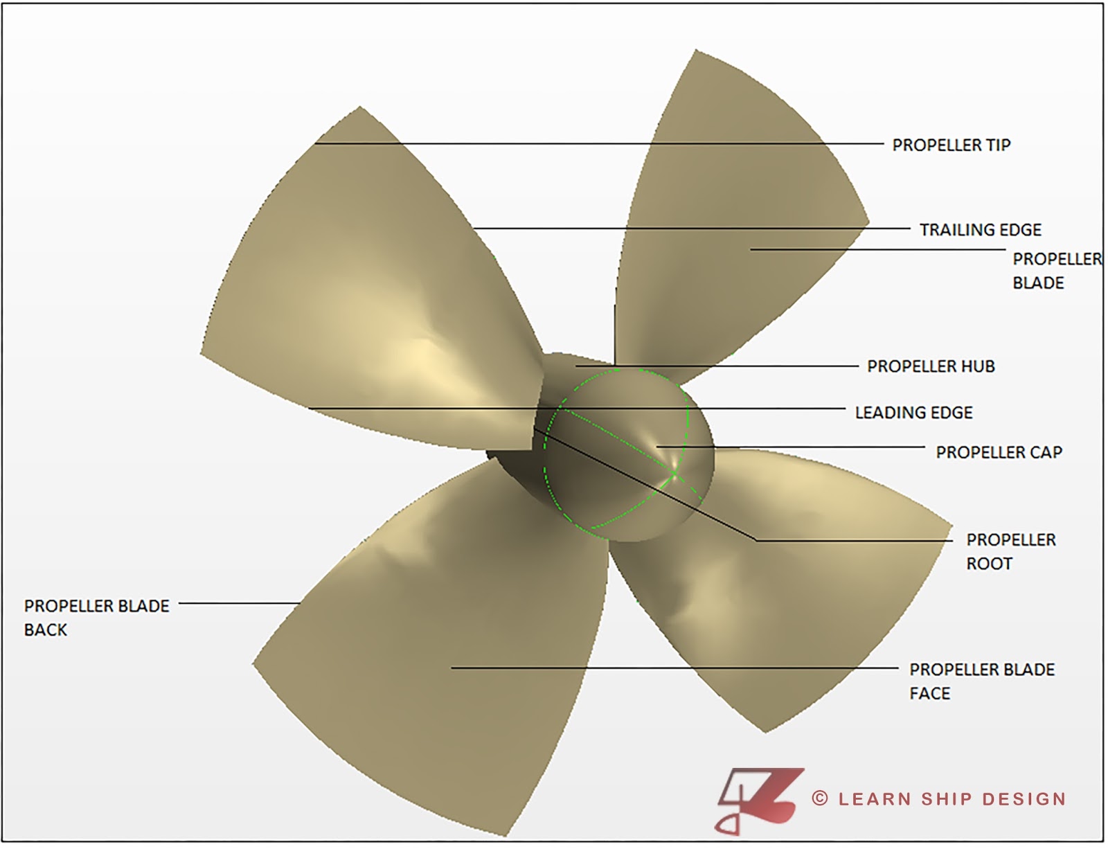
          The side of the propeller blade seen when one observes the propeller from behind the ship is called the face of the propeller. The other side of the propeller blade is called the back of the propeller.
          The narrow end of the boss creates a lot of disturbance as it rotates in the hydrodynamic medium leading to flow turbulence, separations and even hub vortex cavitations. Thus in order to smoothen the flow around the hub tip, a smoothly streamlined cap is provided called the boss cap.
          The axis passing through the centreline of the propeller shaft is called the propeller axis. The part of the propeller blade farthest from the axis is termed as the propeller tip. In the propeller blade, the side that pierces the water first as per the direction of rotation is called the leading edge of the propeller, and the other side that follows the leading edge is called the trailing edge of the propeller.
Image Courtesy: Team LSD.

SCREW PROPELLER- RIGHT AND LEFT-HAND SCREW

Screw propeller whose direction of rotation if is represented by curling of our fingers of our right hand produces thrust along the direction of the thumb finger, then it is called right-hand screw propeller. If a propeller exhibits the same phenomenon for the left hand, then it is called left-hand screw propeller.
          Generally, in most of the ship where single screw propeller is provided, a right-hand screw propeller is used. There is no such reason behind this. It may be considered as a conventional practice. On the other hand for twin screw propellers one of the propellers is right hand and another is the left-hand screw. This is done to negate the circulation produced by one propeller to disturb the flow onto another.

Image Courtesy: Google Images.

SCREW PROPELLER- THE SLIP PHENOMENON

Screw propeller works with the basic principle of a screw, such that with every complete rotation of the screw, it advances by 1 pitch. The only difference being that in a screw and nut pair due to the presence of a solid thread, the nut exactly advances by 1 pitch on one complete rotation of the screw. In case of propellers, the situation is analogous but as the propeller works in a hydrodynamic medium where there is no thread, so the propeller slips. Thus on every rotation, the propeller advances by a distance less than the pitch of the propeller.
Image Courtesy: Google Images.

SCREW PROPELLER- TERMINOLOGIES

To understand screw propellers we must understand some of the characteristic terminologies associated with the geometry of the propeller.

RAKE

We know that propeller is made up of different radial sections joined together and the face of the radial section lies on a helicoidal surface. If the line generating this helicoidal surface is perpendicular to the propeller axis then the propeller blade is said to have no rake.
           Rake is provided to increase the clearance between the stern frame and the propeller blade tip such that the pressure pulses emitted by the propeller blade due to the rotation in the hydrodynamic medium don’t impart vibrations in the hull.
Image Courtesy: Google Images.

SKEW

In the projection of the propeller blade on a plane perpendicular to the propeller axis (projected view) a line is drawn joining the midpoints of the projected sections. If this line is perpendicular to the propeller axis then the propeller is said to have no skew.
           Skew is provided in a propeller to increase its expanded area so that loading on the propeller (Burrill Cavitation Criteria) is less and thus cavitation is reduced. Also due to skew the different radial sections of the propeller don't pass simultaneously along the stern counter of the hull where the disturbances in the wake are high. thus pressure fluctuations are not over a large area and the peak is reduced. Thus skewed propeller performs better in a hydrodynamic medium. 
Image Courtesy: Google Images.

 
PITCH AND PITCH ANGLE

Pitch is defined as the distance the propeller would advance by one complete rotation of the propeller. For a radial, section pitch may be same or different.
Pitch angle (∅) is defined as

            Where,
            P= Pitch.
            r= radial section radius.


CONCLUSION

In this article, I have tried to introduce the readers to the basic terminologies of a screw propeller. The geometrical parameters of a screw propeller will be discussed in the upcoming article. 

This is an informative video of various Marine Propellers prepared by Team LearnShipDesign. Hope you all like it.


Article by- Rijay Majee.