Sunday, 6 September 2015

Types of Offshore Structures

Last time, we were introduced to the design and operational considerations of offshore structures. Now, we will take look at the different types in existence today. Before we go into that, take a recap of the previous article here. Also, you might want to see how fierce the environmental conditions can be in this video given below:


Broadly, offshore structures maybe of two types:

  1. Floating - These offshore platforms are floating in free surface and are movable from one location to another. Examples include semi-submersibles, SPAR platforms, Floating-leg platforms, drill-ships, FPSOs(Floating Production, Storage and Offloading systems)
  2. Fixed Platforms: They are immobile and fixed permanently to one place. These sorts of offshore units have greater strength and relative durability as compared to floating ones. These are operationally irreversible as once installed they cannot be relocated . Examples are Concrete/Gravity Platforms, Jacket Platforms,Tension-leg platforms(TLPs), Jack-Up Rigs etc. 
Fig.1:Image of  a deep-sea offshore installation (Courtesy: www.nyborgfan.com/)
Surveillance of the sea-bed and that of the underlying rocks helps in the development of the strategic sites for the optimum extraction of the resources. Furthermore, the oceanographic and climatic conditions around that region are assessed. Then the topographic conditions pertaining to that particular region along with the critical risk factors probable to the given sea-state gives the outline for the apt installation for the site. The offshore structures maybe mobilized from one site to another, may be erected after compilation of the raw materials and parts or maybe made from scratch at the purported site itself depending on its nature. 
As these offshore structures are high-budget, heavy-duty and long-term projects, umpteen care is taken to ensure its livability in hostile sea state and its long term life span.


Fig.2:Image of  a semi-submersible offshore installation (Courtesy: www.offshoreenergytoday.com/)


Jacket Platforms
                                       
These platforms are quite common and comprise of an outer jacket-like structure of welded tubular steel. Steel jackets are vertical sections made of tubular steel members, and are usually piled into the seabed. The pipes are about 1 to 2 m in diameter and have a maximum penetration of about 100 m. They weigh about 20000 tonnes. This external steel jacket has many functions ranging from stability and supporting the entire structure to protecting the internal piping and drill equipment from external disturbances.

Design Parameters 

These steel jackets have tapering, truss-like structure with high strength, durability and fatigue resistance.Loading and life cycle apart from diameter, penetration, thickness and spacing are taken into account. 
  • In a typical design , the cross-sectional dimensions are about 70*65 at the seabed and 56*30 at the top. 
  • They have capacities of resisting forces up to 50 MN in compression and 10 MN in tension and has a large vulnerability to lateral loads like expansion and hydrodynamic stresses. 
  • They also have a maximum permissible overturning moment up to 10 GN.m in most cases.   
The jacket design and the pile design are the crucial factors in determining the total performance of the structure and the total cost in its design and maintenance can devour up to 40-50% of the total cost estimation. 
One point to ponder upon in jacket structure is the protection of the steel from rust and corrosion, a "disease" of all marine vehicles and structures which is principally to be taken care of . This can be done up to a certain extent by using high-grade "stain free" steel and by repeated cathodic protection. 

Jack-Up Rigs

Jack-Up drilling rigs are a type of self-elevating, mobile platform capable of raising the hull part which is obviously buoyant above the sea level and penetrating its steel legs into the sea-bed for support for deep sea drilling operations. The name "jack-up" is derived from versatile nature of the legs or jacks which can be suitably jacked above or below the hull accordingly when not in operation and when in operation. 
These Legs maybe piled into the sea-bed or maybe placed on large footings for better grip and stability. There maybe three or four legs for jacking up the buoyant hull above the sealevel for operations. After a stipulated time period after termination of the operations at a place, the legs are dismantled from the sea floor and are jacked above the hull and the entire unit is mobilized to another destination maybe to some jetty/port or to another drilling site. They are not self-propelled and usually depend on tugs of Heavy Lift Ships for towing from one place to another.
Well when and where can jack up rigs be used? The answer IS that they maybe used in shallow waters as pre-operation and post-operation mantling and dismantling of the jack ups are very bleakly feasible in deeper waters. The steel legs are of high strength HSS steel and are  designed to confront wave dynamics even in rough seas up to a certain limit. Care must  be taken for their maintenance in terms of corrosion, fatigue, stresses. In case of sea or external parameters going beyond the tolerance level, these are immediately "jacked up" and are shifted to safer locations or kept in a safe nonoperational, dormant mode. 
Jack -Up rigs are used specifically for oil well drilling purposes and has limited or no storage capacity. Storage or bulk transport may be through oil tankers or the multi-purpose FPSOs (Floating Production, Storage and Offloading Units).  

 Fig.3: Basic Components of a Steel Jacket Offshore 
Structure (Copyright: Maersk)    
 

Concrete Platforms/Gravity Platforms

Concrete Structures are purely composed of concrete and is considered the safest mode of offshore industrial operations. They maybe directly fixed or molded to the sea floor on a permanent basis or maybe floating. 

Fixed ones are also known as Gravity-based structures or the Caisson type. The entire structure is based on a submerged island-like solid structure which may serve as a foundation structure as well as storage or oil or other by-products. The entire load of the structure acts directly on the subsequent  layers of the sea-bed eradicating problems even of the extreme wave disturbances or seafloor scour. On the other hand the floating ones are freely float-able and has six degrees of freedom under a proper mooring system.  

Some designs of these concrete structures are Condeep, ANDOC, Doris and so on. The design parameters are guided by the number of supporting columns and the diameter of the legs. Constructing is a tedious process where the entire structure or its components are towed and assembled with proper ballasting and de-ballasting measures. They have almost negligible maintenance and high durability. Can be also used for greater depths. 


Fig.4: Garvity based Offshore Structure 
(Courtesy: www.paroscientific.com/)
Fig. 5: Concrete fixed platform (Courtesy: www.wind-energy-the-facts.org)

Compliant Towers 

Whenever the word "compliant" comes to our mind we mean a sense of complying or yielding. These are tall, slender, single isolated structures with high slenderness ratio.
They are comprised of specialized flex tubes of 2 to 7 metres in diameter comprising the space-time frame-like truss  with high degrees of flexibility and can withstand high amounts of lateral loads up to 10 feet  due to waves or oceanic disturbances. 

The rig consists of narrow, flexible (compliant) towers and a piled foundation supporting a conventional deck for drilling and production operations. They are mainly operated in depths upto 1500 to 3000 feet. They inherently have a frequency lower than the natural frequency of the waves, such that with the emergence of any wave disturbance can make it oscillate with a resultant frequency safer for the loads and eradicate the probability of any resonating conditions. They work on a principle of de-amplification of waves dissipating the energy responsible for creating greater mayhem. Hence they are applicable for high tide or even the worst sea conditions.The lower part of the frame depends on the pilings and can penetrate hundreds of feet below the mud line. 


 Fig.6: Different Compliant Structures through the years (Courtesy: www.atp.nist.gov/)

Tension-Leg platforms

These are floating facilities which stay afloat and remain in position with the help of specialized steel tubes called tethers or tendons. These are nothing but the supporting legs of the floating platform which by the virtue of their upward tension takes care of the position, loading and the functionality of the extraction system. For all such tension leg platforms there is not much vertical oscillatory motion of the platform how rough the sea conditions or the average wave height may be. This facilitates in tying with the wellheads and the piping system for extraction of oil without much distortion. for all such systems there is always an additional buoyant force which keeps the platform afloat. Thus for all such installations,


Tension =Buoyancy - Weight

Here topside facilities and the basic parameters like the number of risers have to be fixed at pre-design stage. Generally the platform is manufactured on the shore and is towed to the desired location with the help of tugs. This structure is apt for depths up to 1200 metres and has limited or no storage facility. As of common usage, these have a high maintenance and surveillance cost of the tethers and under unavoidable circumstances the structure may be prone to irreversible damage. 


Fig. 7: Structure of a typical tension-leg platfrom (Courtesy: www.slideshare.com)


Semi-Submersible

They are floating installations which rest on four or six pillar-like legs called columns with a equal weight distribution on each. These columns or legs are in turn attached to large basements called pontoons floating on the water surface. These pontoons may be ballasted or de-ballasted accordingly on and off operations. Often these pontoons delve deeper under the water surface and maintain the buoyancy and position of the floating system. There is always a greater draft. Thereafter the operational deck is kept well aloof from the wave disturbance or the rough seas.However due to small waterplane area the structure is sensitive to load variations and must be trimmed accordingly. They by the virtue of their equivalent weight distribution and a high draft, it has a greater stability than normal ships. The number of legs, pontoon design , the situation of the risers and drill equipment are decided at pre-design stage. They are generally instrumental in Ultra-deep waters where the fixed structures pose a problem. Their position is maintained generally by a catenary mooring system or sometimes in modern structures by Dynamic :Positioning System. These structures are gigantic and may be towed from one location to another by the virtue of a kind of ships called Heavy Lift ships. 

                                                                                  
Fig. 8: Semi-submersible Offshore Platform (Source: patentimages.storage.googleapis.com)


Fig. 9: Heavy Lift  Ship (Source: www.motorship.com)

SPARS


These have a large diameter cylindrical deck supporting the main deck .They are generally developed as oil platforms for deeper waters as an alternative to the conventional systems. Most of the drilling and oil extraction equipment are situated within them. The inside part of the cylindrical truss is filled with some material denser than the sea-water to lower down the centre of gravity and hence maintain the vertical stability of the structure.  The deep draft design of spars makes them less affected by wind, wave and currents and allows for both dry tree and subsea production. The cylindrical structure is surrounded by helical strakes to avoid vortex-induced motion. 

The first prototype of the SPAR Platform was Neptune laid off the US coast in 1997. 

There are basically three types of spars, namely, truss spar, classic spar and cell spar. 

It is generally equipped with taut catenary mooring and the heave natural period is generally below 30 seconds. Generally , the  spar is employed for depths up to 2300 m. The number of risers is restricted generally due to the limited space of the core cylinder. These are highly stable and hence are negligible unaffected even on adverse sea conditions or sharp environmental vagaries.  


Fig. 10: A typical deep sea SPAR Platform (Courtesy:www.maritimeconnector.com)


FPSOs

FPSOs stand for Floating, Production, Storage and Offloading Systems. It is a specialized vessel for the purpose of offloading, processing, storage, distribution of oil and other hydrocarbon resources. One important point to wonder is that these installations does not have anything to do with the extraction purposes and can be merely reckoned as a carrier with specialization. These vessels eradicate the need of long pipelines for transfer of oil and petroleum to the shore. FPSOs are preferred in frontier offshore regions as they are easy to install, and do not require a local pipeline infrastructure to export oil. FPSOs can be a conversion of an oil tanker or can be a vessel built specially for the application. A vessel used only to store oil (without processing it) is referred to as a floating storage and offloading vessel (FSO). These can operate extensively in remote and deep waters and also in marginal wells where fixed platform or piping is technically or economically not feasible. 
In majority of the cases the vessel may be buoyed to a vicinal drilling platform. Also the oil or other petroleum products maybe transported to the mainland by pipelines or by a conventional mooring system. The vessel may be fixed in a particular position by mooring lines or by a dynamic positioning system (DPS). 
                                    
                                                   
Fig.11: The ongoing operations to an FPSO and the production process

Fig.12: Floating production storage and offloading unit (Courtesy: www.alibaba.com)

These ships have an integral storage capability inside their voluminous hull and have a calculated freeboard and draught. They are operational in adverse weather  and have a high maintenance cost. 

Drill ships

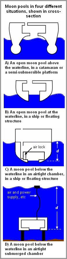
It is a mobile offshore installation akin to a ship which is specialized for exploration and drilling of oil and gas resources more specifically for scientific exploratory purposes. Mostly, it is used for deep and ultra deep applications involving exploratory and drilling purposes. The first drillship was the CUSS I, designed by Robert F. Bauer of Global Marine in 1955. The CUSS I had drilled in 400 feet deep waters by 1957.Apart from regular drilling purposes, the drillship may also be used for maintenance and surveillance purposes such as casing and tubing installation, subsea tree installations or wellhead capping. Drillships though expensive and of high precision in operating and maintenance, is often believed to be the most proficient mode of offshore technology trend where like any conventional ship, it can be transferred from one place to another anytime and that too without the use of any tugs , heavy lift ships or any other towing system. However a mandatory mooring system should be kept or a DPS positioning system  should be employed. Generally, underneath the derrick through the hull is the moon pool which connects the deck to the sea directly. Sounds pretty interesting, isn't it ? The moonpool is generally an opening of the deck floor with the water in any marine research vessel, drillship, sometimes icebreakers, diving support vessel for easy exposure to the underwater environment or for the easy steup of the drilling equipment as done here. Generally moonpools are situated in four different positions, above the waterline, at the waterline, underneath the waterline or deep submerged depending upon the requirements, the vehicle or the design. So, for a drillship the moonpool provides easy accessibility for the drill equipment or manpower for the purpose of maintenance of the drill equipment or underwater survey. However immense care has to be taken during the design stage to ensure the moon pool compensates the loss of strength in the deck or hull, maintain stability and trim and avoid flooding or leakage. 

                                                              
Fig. 13: Different types of moonpools (Courtesy: www.wikipedia.com)


A simple way to understand what a drillship is to do in order to drill, a marine riser is lowered from the drillship to the seabed with a blowout preventer (BOP) at the bottom that connects to the wellhead. All this is done through the moonpool intricate to the hull. Drillships also have their own storage and processing system . However, in terms of positioning and stagnancy during drilling operations, the semi-submersibles have an upper hand. 

Fig. 14: A TIGER Series Drillship (Courtesy: www.offshoreenergytoday.com)

This was all about the common types of offshore structures in existence today.LSD


Article By: Subhodeep Ghosh

Sunday, 30 August 2015

Know A Ship- Heavy Lift Ships

How would you move a gigantic oil rig from one place to another after installation or after dismantling? Or how would you transport a large passenger vessel with its hull damaged beyond vulnerability and exhausted of the very chances of mending it on-spot? Well, the first impression that enthuse us is the applicability of tugs or similar towing systems. However, everything has its own limitations and sometimes the situation demands that we bank on other options more inventively. Necessity is the mother of invention. So, one of the most tantalizing outcomes in the shipping world is the Heavy Lift Ships.By definition, they are specialized ships that carry out tedious heavy load in-taking operations that cannot be handled by normal or regular ships. They are segregated into two types : semi-submerging vessels capable of lifting another ship out of the water and transporting it; and vessels that augment or cater to heavy unloading facilities at inadequately equipped ports. 
Fig.1 Heavy Lift Ship carrying a cylindrical SPAR Platform(Source: www.dnv.com) 

A Brief History of Time

In the early stint of the previous century, most of the existing offshore technologies like rigs, platforms, oilwells, floating drydocks, drilling rigs,etc. were directly towed across the seas in what was known as "wet tow". The mobilization was long, tedious,cumbersome and often posed risks of on-voyage damage. By the end of the 1960s,the towage companies realized that  if they could manage a large barge-like vessel that would carry on themselves all these bulk items in what was conceptualized as the " dry tow", things could be easier. There was this ideal of carrying a floating cargo as a cargo on another floating object! All these had a bottom reaction" having a capability of a submergence stern resting on the seabed.  In 1976, a renaissance was sparked off when the first heavy-lifter semi-submersible  barge  'Ocean Servant I' entered the heavy lifting market. the induction of the buoyancy casings at the four corners enabled it to remain afloat and submerged without the need of bottom reaction. It had two 500-hp omni-directional propellers and was still self-towed. In 1979,the 1st self-propelled semi-submersible mighty barge 'Super Servant' came into the limelight.
It had a depth of 15 m , 6.5 m water level above the deck and had ballasting and de-ballasting features automated. Further down the timeline, in 1983, three 'Mighty Servants' with more advanced mechanisms and larger cargo-carrying capacity formed the most versatile class of the Heavy-lifters. A stark feature of these trio was the presence of three buoyancy casings which were removable. April 1985 saw the birth of two more of its breed namely, the 'Dan Lifter' and 'Dan Mover', which were rechristened Super Servants 5 & 6. By that time, technology had strode further with Heavy Lifters gradually acquiring the stake of major heavy lifting operations which also saw a further up-soar in the field of offshore like more semi-submersibles entering the deals. With doing away with stowage, mightier structures could easily be shouldered by these marvels and that too much easily by having the deck margin line absolutely parallel to the keel of the cargo. In April 1990, the ultramodern Heavy Lifter made by Russia 'Transshelf' created an upheaval in the revolution of modern Heavy Lifters. 


Why heavy lift ships and how?

Heavy lift ships to be precise are hefty and ginormous special-purpose vessels that are about 3000 times the capacity of a blue whale! Sounds quirky, isn't it? They miraculously have a lifting capacity of over 10000 tons. These ships have a large, wide and longish carriage deck which is mainly allowed to submerge below the water line and large bodies like oil rigs or whole ships are allowed to float on it or mounted on a dry dock. The alternation in freeboard and buoyancy is carried out by suitable ballasting and de-ballasting practices. The deck, henceforth comes out or remains submerged in water in such cases. Probably, you may wonder out of curiosity as to how the ship still remains unsinkable even after carrying such brawny loads. Well, we do give a quick glance at one of the most quintessential aspects naval architecture namely, draught, floatation and buoyancy .

A brief recall of Buoyancy and Displacement


We all since our good old school days are not alien to a fundamental concept of Archimedes' Principle. According to the statement, it is said that : "When a body is completely submerged in a fluid, or floating so that it is partially submerged, the body is subject to an upwardly acting buoyant force, which in turn is equal to the weight of the fluid displaced by the body."
In other words, irrespective of the shape, size and other parameters of the body this upthrust or Buoyant force acts vertically upwards opposite to its weight. This force acts through the geometric centroid of the body and this particular point is christened as Centre of Buoyancy  of the body. Though I do not delve much into the mathematical content and its diversities for different scenarios, one important thing we must confide is that not just a light paper but even the heavy lift ships weighing over 10000 tons obeys this classic principle thereby accounting for its habitability. Hence, if you do have a myth about these structural giants, do get rid of it! Even these hefty giants about 3000 times the size of a blue whale float like a normal paper-boat!Finding it a bit weird to be true? The phenomenon is the same old buoyancy governing all other marine vehicles. The displacement or the volume of water substituted by the submerged body accounting for the validity of Archimedes' Principle is the main governing factor.So, heavy lift ships having a large scale displacement of the order of 10^5 square ms.have a large upthrust and the draught varies within certain limits depending on the temperature and salinity parameters of the water and also the load. 


 Fig. 2 Buoyancy and Archimedes' Principle(Image Courtesy:Google Images)


For high stability and to prevent heeling of the vessel sideways, stability is a quintessential aspect in such heavy lifting operations about which will be discussed shortly. However for a simple piece of reasoning that a ship does not lose its trim and tilt at one end, there should be a uniform weight distribution. Hence for a Heavy Lift Ship, the load is generally kept on the larger span of the weather deck which on many occassions remain submerged beforehand to handle larger displacements(and hence larger load capacities). 


  Fig. 3 Floating of a ship and its loss of floatation (Image Courtesy:www.schoology.com)


Fig.4 Heavy Lift Ship carrying a smaller vessel.Has a submerged main 
deck (Image Courtesy:www.amusingplanet.com)

Stability factors in Heavy Lifting Vessels

Loading and heavylifting operations in vessels are not only a matter of how much load a ship can carry but how much does it survive under this load. If you are simply allowed to troll on a walkway with a medium sized brick you may do that easily. But what if the load is being increased persistently and if you are asked to carry a tree trunk ? The probable answer from the majority is that can't.But if momentarily you imagine yourself to be a giant and somehow manage to lift it up, what will be your status? Will you manage to keep yourself upright? And even if so, till how long? Suppose, someone gives you a slight push. Will you be there like before or tumble over? Well same is the case of ships. Stability is an inherent factor for a small boat as well as a heavy lift vessel. In a completely undisturbed condition, or in an equilibrium case, a a given displacement the buoyant force balances the weight acting vertically downwards. Hence in such a case , the centre of gravity(C.G.), the centre of buoyancy(C.B.) and the geometric centroid( which in almost all the normal cases coincides with the centre of gravity) lie on the same line. In such a case, the ship is said to be stable. Considering some external disturbances like wind or some high waves, the stability is said to be lost. Although, by property the C.G. remains intact the position of the C.B. changes. The point of intersection of the original line passing through the C.G and the initial C.B. with that of the line passing through the final position of C.B is termed as the metacentre M.


Fig.5 The position of the various points in an unstable  condition (Courtesy: www.marineinsight.com)


In all such heavy lifting errands, like in heavy lift ships, there is a rigorous change in C.G due to loads and also due to operations like lifting through cranes or derricks. This uneven distribution of weight in all such ProjectCargoes often cause the C.G. to be on either side of the centreline. Hence the ship has a high probability to heel towards that side. On normal day-to-day ferries or other ships, the stability mainly gets lost due to two reasons; either shift of C.G due to uneven loads or direct and abrupt change of C.B. due to external conditions leading to heeling. However, in heavy lifting operations, mainly, the culprit is the biased CG.

On one side that causes the vessel to list henceforth. As depicted in the above figure, there is a normal GZ, from the initial C.B to the line passing through the final C.B and is called the righting arm. This can cause a righting moment to the ship and may attain back its position. A negative GM is always uncongenial for the ship which may lead to its capsizing of the ships( which is a pertinent disaster !). Also by the virtue of a reverting counter buoyancy, the ship may, in certain chances attain back its stability,i.e, become upright. This tendency of a negative inherent stability is measured in terms of a certain Angle of Loll. It is the state of the ship which is unstable when upright. It has a dramatic property property to lurch to another side on the action of external forces producing the same value of Angle of Loll on the opposite side. Remember, do not confuse it with list!! Listing is caused by the sifting of cargo and material grain causing a change in C.G of the body. But this counter event  called Loll is just a reaction force in counter to Rolling. In case of a suspicion that the vessel might be subject to Loll, we must do something which may sound quirky! Ballast or do some weight additions to that side which has the loll or the greater inclination downwards. This dramatically depletes the severity of the Angle of Loll, but provides a boon at the end.The draft increases drastically and the freeboard decreases along with the so-called free-surfce effects.  The C.G. immerses further and the greater submersion of weight increases the "Buoyant Reaction", which in turn creates a negative Angle of Loll at that condition. 
                       
                                                        
Fig.6: Angle of Loll(Source:Googleimages)

Another simpler implication is to just undo the cause for this loll.Mainly, the majority of these events are caused by heavylifting activities on the superficial weather deck that drastically shifts the Centre of Gravity to the heavy load carrying side. Cranes, Derricks or other facilities carrying out these operations are the other culprits, which along with the weights they are carrying act as moment arms, causing a resultant tilt. Maybe, the following image explains it better!


Fig.7.: Heavylifting operations on a ship and the resultant shift of C.G (Courtesy:www.sphlashmaritime.com)

So, for a heavy lift ship, care must be taken while loading and offloading operations in the deck such that the ship is free of loll. As a Heavy Lifter is designed specifically for loading purposes, it is not as if heavylifting operations should be avoided. But the weight should have even distributions and as it involves weights in the order of 10000 tonnes, things have to be in line! Most of these have modern ballasting technologies,thrusters and Dynamic Positioning Systems. Heavy Lifters, an alternative to the older technology of heavy lifting cranes or projection cargoes straddle the cargo(jackets, rigs, oil wells, semi-submersibles, ships etc.) uniformly on both sides and allow proper suspension of weight in a manner that avoids Loll or list under normal circumstances.

The Cargoes and its Sea keeping moves

The versatility of the Heavy Lifters coupled with its mammoth capabilities enabled it to be the workhorse for several varieties of cargo like the floating plants, drydocks, rigs, Pressure vessels,cranes, jackets just to name a few. Even the navy vessels which were of high precision were often transported by the virtue of these which substantiated their flexibility. The serviceability limit weights by the order of 4000-5500 tons which leapfrogged to 21,000 plus tons for the largest rigs in the modern days. Marine technologies which has contributed significantly in the revolution of these vessels, has further diversified along with the modern day computational software for complex motion and vibration responses. These ships are subjugated to a high ordeal of strength and endurance testing which affirms its competence in their operations. Well, model testings are an indispensable part in any form of engineering and large scale productions. Heavy lifters are not an exception with motion response tests which are objected to mainly test the non-linear behavior of the ships in rolling motion. 
Some of the important cargoes which have been transported so far by these ships are:


·  Jack-ups ' Norbe 2 and 5 :

 In 1988,  these two mighty jack-ups were transited from Salvador, Brazil to Mumbai( erstwhile Bombay)in India. They had a projection lengths of 4.5 metres and had spud can diameters of 14 metres. If not for these ships, then the net transit time would have been a matter of 150 days. The footings posed a great deal of trouble and in case of direct stowage would have resulted in a drag speed of 3-4 knots which would have made things cumbersome. These were carried out by the 'Mighty Servants 3' and made it possible in a matter of a little over three weeks( almost a month!)The legs were for stability placed on the cribbling blocks for the ease of dynamic loading. The lower deck was cut off to accomodate the rigs upto the safe submersion limit and seafastenings were provided on the aft legs of the rigs. 

·  Tension-Leg Wellhead Platform : 


In 1989, the first ever Tension Leg was transported by the Heavy Lift from the U.S Gulf. It was carried out by the same 'Mighty Servant I' was a float-on type of loading mechanism. The truss deck was carried out by four columns each of 12.2 metres in diameter, 46.2 in height and was a space frame structure of spacings in the order of 42.2 metres. Pontoons, about 7 metres in diameter connected the columns near the base. 

·  Challis Field SALRAM : 


The Challis mooring system consisted of a 121 metres riser attached to a 34 by 34 gravity base structure. This base structure weighing about 4500 tons was put to board on 'Mighty Servant 2' around mid of August 1989. To facilitate the proper spacing, the ship's starboard buoyancy casing was shifted forward to accommodate the entire structure. 

·  Damaged Tanker 'Imperial Acadia' :


You all must have pondered upon the speculation of the operational ships, vessels and structures from one place to another as per the convenience. Have you ever wondered what would happen if a heavy, expensive and high-precision vessel is stalled amid the sea? Or some parts or crucial machinery are broken down? Wet Towage across the seas would be a pursuit of money, time and most importantly a factor of greater risk. If physically some parts of the structure is seriously damaged, forcefully towing it across the rough waters would exalt the chance of damaging it further. Many of the naval vessels or crafts when damaged are carried up by the Heavy Lift Vessels as they are of indigenous design and mechanisms worth millions. A lot of U.S Navy minesweepers have been barged up on 'Mighty Servants I, II and III'. The demobilization of the Canadian giant 'Imperial Acadia' de remains a milestone in the achievements of Heavy Lifters. With a length of 135 metres, this high capacity Canadian Tanker was caved 1.5 to 2 metres on the lower starboard side in the event of a frivolous sea-storm near a french island. Mighty Servant  I performed the tedious task of safely towing it on-board to a shipyard in Halifax for hull repairs.


·  Floating Drydock 'Karish' : 


Drydock facilities are developed generally for still water conditions. Hence forth their mobilization in wavy, gushy seawaters account the dynamic water loads acting on them. So mobilization through the Heavy Lifters through 'dry tow' which affixes it above water eradicates the need of greater steel strengthening or severe damage in case of accidental loads. The offloading of 142 metres long, 7500 tons heavy the 'Karish' dry-dock at Batangas, Philippines by Transshelf Heavy Lifter is reckoned as a notable event in the history of Heavy Lift Ships. Today several such drydocks or floating jetties, ports are shouldered upon by them in case of their relocation from one place to another.


The Reigning Giant-Dockwise Vanguard

The Dockwise Vanguard is the largest Heavy Lift Ship which is owned and operated by the Dockwise B.V. A sprawling 70 by 275 metres  flat upper deck, it can lift upto 110000 tonnes of weight. Its propulsion is by the virtue of 2 giant propellers, 2 retractable azimuth thrusters and a powerful bow thruster. Launched recently on 7th October 2012, the Vanguard has earned its repute by transporting huge offshore rigs,gas facilities and other enormous vessels. It is a semi-submersible vessel that can immerse its principal deck up to 52 feet below the water level in case of deep draught cargoes. It is equipped with four strong buoyancy casings and can handle cargoes at varying depths by their ballasting measures. Some of the structural giants which were pillion on Vanguard were the Chevron's St. Malo Oil Platform, the Goliat FPSO and the Aasta Hasteen Platform, the latter two being born to Hyundai Heavy Industries Ltd. 

                                                   
Fig. Dockland Vanguard (Source: Googleimages)

Next but not the least- MV Blue Marlin


MV Blue Marlin, as you must have heard is the second largest ship owned by the Netherlands Shipping corp Dockwise. It has a length of 224.8 meters, beam of 63.1 meters and a permissible draught of 13.1 meters. It has a deadweight of over 76000 Tons dead weight. Some of the notable cargoes of this giant were the American Destroyer USS Cole, oil platform Thunderhorse and the amphibious Australian warship HMAS Canberra, just to name a few.LSD
          
                                                        
 Fig. MV Blue Marlin (Source: Googleimages)

Article by: Subhodeep Ghosh

Thursday, 11 June 2015

Design of Offshore Structures


Over 3/4 the of the earth's surface is made up of water. So, with the insatiable needs of the of the ever-increasing population globally it reckons mankind to not just bank on this meager fourth area for our resources but also hone our capabilities into the wilderness of the oceans. The oceans as we know, are full of resources. So, effective tapping and exploitation of these resources on a long term basis can meet our pressing energy needs.Offshore structures are one of those installations and facilities in the deep ocean at strategic sites for the exploration, exploitation and large-scale production of natural resources like oil, gas, minerals, electricity etc.
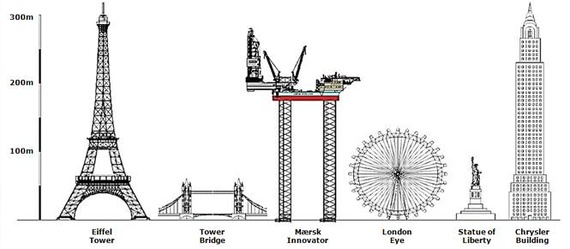
Fig. 1: Infographic comparing sizes of a typical offshore structure with other man made megastructures. (Courtesy: cdn.theatlantic.com)

For the past several decades, the increase in the quest for exploitation of petroleum resources has lead to an extensive spatter of these offshore resources all over the world.

Offshore Structures: A Detailed Synopsis


In simple definitive terms, offshore structures are man-made installations in the resource-rich sites in oceans for the purpose of exploration, exploitation and production of petroleum, oil, gas and other power and energy resources. Generally, all offshore platforms have: 
  • A superficial structure, mostly above the water level consisting of operations,  machinery, accommodation, control systems, piping systems, etc.
  • An intrinsic underlying  system consisting of drilling equipments:  drill bit, drill collar, risers and conduits, wellheads for the purpose of extraction of oil from the sea bed

Parts of an Offshore Platform

An offshore platform deals with topside facilities as well as the underlying drilling facilities. The topside facilities lying above the sea level involves an optimization between  space as well weight yet involves all the neccesities for the oil extraction purposes. The ambient components of any offshore platform involves derricks, drilling rigs, oil storage facilities and tanks, injection compressors, gas compressors , gas turbine generators, HVAC,  Piping, Instrumentation, Basic machinery like primary and auxillary power generators, cooling system, pressure regulation etc. Also worth mentioning are control wheelhouses for operating personnel, suitable accommodation and helipads. Cranes and lifting system for loading and unloading operations are also there.
In the undersea extraction systems, some of the terms worth mentioning are drill collars, drill bits, wellheads, conduits, risers, BOPs, etc. Though not complicating stuff about the details and description of each of these, drill bits and collars involve drilling into the sea bed to create the oil well for extraction. On the other hand, wellheads provide structural and pressure containing interface at the opening to any oil or gas well for drilling and production.
Risers are components synonymous with any drilling platform inherently. This is basically a conduit that provides an extension from wellhead subsea to the drilling system above. They are basically of two types: marine drilling risers for floating platforms or tie-back drilling risers for fixed platforms. Risers have the catalytic role of conducting the crude oil or gas from the wellhead to the drilling rig by the virtue of a piston like mechanism which in turn is sent to the above rig for processing. The design of the riser depends on the filed layout, vessel interface, fluid properties and environmental conditions. Risers maybe flexible or rigid. Also  they remain stable and in tension due to self weight. They may have profiles to reduce excess load and nonviscous fluid flow.


Mooring and Anchoring


Given the varying sea conditions and the environmental vagaries, for proper positioning, ease of operation and safety , mooring facilities have to be initiated. Mooring may be by the virtue of steel or synthetic mooring lines. Steel ropes having high strength and rigidity have catenary nature and may use more length. On the other hand synthetic mooring lines are elastic, taut -shape and uses lesser length.


Fig. 2: Different parts of an offshore structure with piling arrangements.  (Courtesy: www2.southeastern.edu)

Also corrosion is a big setback for stell ropes as compared to the synthetic ones. The platform may also be under certain conditions be anchored or held fixed to a jetty or pier if possible. Drillships, FPSOs or sometimes semi-submersibles mostly use DPS (Dynamic Positioning Systems) systems for positioning. 

Loads on any offshore Structure

Any offshore structure can be subject to various loads like:
  • Permanent Loads
  • Operating Loads 
  • Environmental Loads    
  • Construction
  • Accidental Loads
Permanent loads involve the construction loads like the weight of the entire structure, ballast systems, weight of machinery, accomodation and other equipment. For members below the waterline it involves the hydrodynamic forces and also the hydrostatic pressure forces like the buoyancy and pressure loads.
On the other hand, operating loads involve the loads subservient under the ongoing operations like  loading and unloading, drilling, mooring operations, additional loads generated by cranes and derricks.They take into account impact, momentum, vibration, slosh dynamics, material fatigue etc.  Also involves weight of manpower,equipment, storage like the crude oil which has been extracted, life-support systems and so on.
Environmental loads may be subdivided into the various categories like

  1. Wind Loads : These loads act on the above portion of the platform by virtue of the blowing winds of varying extremities.For instance during regular sea breeze, this aspect is not to be taken care of but where the situation is graver like in case of gale storms ruffling the seas hither and tither, the consequent aftermath on the structure is a pressing concern. Especially when height to width ratio is more than 5, the cyclic wave loads due to the induced vortex flow has to be taken seriously into account.Structural members have to be designed such that they can withstand longitudinal loads with greater endurance than transverse for higher slenderness ratios.Snowfall or frost heaving which is a phenomenon of abnormal swelling of soil during cold temperature may pose a potential threat to the structure.
  2. Temperature and Atmospheric Pressure loads cause thermal expansion, contraction and sometimes deformation. Suppose a platform amidst the cold northern Atlantic during winters have ti endure high amount of low pressure and temperature vagaries while somewhere near the Tropics during summer, it may be subjugated to high temperatures, pressures, humidity or warm underwater currents sometimes leading to expansion. 
  3. Seismic Activities often take place in the underwater oceanic plates where they drift, vibrate, intimate or recede away from each other. These oceanic seismologic behaviour which often leads to climate change and variance in the ocean wave mannerisms have a detrimental impact. Sometimes these oceanic activities pave way for catastrophies like the Tsunami which may be fatal. 
  4. Lateral Loads from soil , groundwater or seabed may endanger their piling or foundations hence often aggravated by seafloor scour. 
  5. Wave loads are the most prominent terror that poses threat to all offshore structures. The ceaseless oceanic activities at the surface from light ripples to gigantic waves are a matter of vast study which I do not include in this article. Only I would mention that the waves are basically gravity contact forces energy transfer phenomenon that occurs due to wind pressure on the water surface with a given force or speed, duration and fetch(distance over which the wind blows). Waves may be of internal or external type or maybe normal sea waves, swells or breaking waves.Technically, the total wave forces on larger, broader structures maybe through diffraction theory while that of slender bodies with D/L ratio greater than 0.2 and considered hydrodynamically transparent use Morrison's equation for calculating wave impact. Thus the preliminary design of any offshore structure takes care of its resilience to the waves it faces. 
  6. Marine growth accumulates on the submerged surfaces, increasing the wave forces through higher drag forces and surface roughness.
                                             
                                                 
 Fig. 3: Wave disturbances in water surface (Courtesy: www.pbslearningmedia.org)


Installation Loads


These are temporary loads that arise during the fabrication or erection of the platform or its components. During fabrication erection lifts of various structural components generate lifting forces, while in installation phase, forces are generated during platform load out, transportation to the site, launching and upending, as well as lifts related to installation.
Fig. 4: Offshore Structure receiving minor repairs from shore supply vessels.  (Courtesy: www.theneweconomy.com)

All lifted system loads may be suited to withstand the loads of the material as well as sustain the static equilibrium of the lifted component, the slings in tension and the entire system. Other forces involve the drag forces to a jacket when transported from the fabrication yard to the site or tugging a completed semi-sub by a Heavy lift ship. Also another crucial aspect taken into account is the final "fixation" of the structure like in case of a jack-up plunging its legs to the sea-bed, or while mooring a semi-submersible or while merely clamping the legs of a jacket platform to the sea-bed through piling foundations. These activities often generate terrible heave motion which unrestrained may lead to operational failure or even collapse of the structure. 

Accidental Loads


To err is human. If we go by these words in our day-to-day lives, such multi-purpose projects are not out of the bag. According to DNV, accidental loads are loads which may occur as a result of pure accident or exceptional circumstances. So, the worst instances may be collision, breakage, flooding of buoyant parts, fire or explosion. Since the majority of offshore platforms deal with oil, gas , petroleum which are inflammable storage and productions needs to be with umpteen care. Evacuation measures need to be implemented in case of the unwarranted.
Fig. 5: Firefighting operations in progress in the vent of a major fire onboard the structure.  (Courtesy: abc.net.au)

Fire extinguishers and proper recovery equipment should be handy to combat any hazard and revert to the recovery process as fast as possible. 

This was all about design considerations for offshore structures which every offshore engineer is always aware of. The next time we will take a look at the different types of offshore structures in existence. Oh, and before leaving, do not forget to follow the youtube link for an exciting documentary on these 'Megastructures'.LSD


Article By: Subhodeep Ghosh