Pages - Menu

Sunday, 26 April 2015

X-BOW: Beyond the Conventional

With increasing prospects and demand for speed comes revolutionary changes in design and advancements in technologies. One such change which made a splash in the maritime industry was the introduction of X-bow by the Norwegian Ulstein Group. Since the inception of their first ship M/V Bourbon Orca in 2005 several other ship building yards/companies have used their design.

The X-bow comprises of a backward sloping bow starting at the extreme front of the vessel. This results in a continuous and smooth bow shape as shown below. Designing such a vessel involves proper weight distribution in the forward region which allows for submission and sharper bow shape. Increased volume up front allows it to efficiently respond to larger waves.

                                       (M/V Bourbon Orca, image courtesy: Ulstein Group)
                                         
So, what are the factors that make X-bow better than the conventional? Let us see.

  • Better comfort and efficiency - model tests by the Ulstein Group at MARIN revealed that the short duration of speed loss due to wave impact is almost negligible, giving the captain the confidence to sail at higher speeds.
  • Lower level of vibrations.
  • Lower resistance due to absence of flare.
  • Better dynamic positioning due to lower wave-drift forces at zero speed compared to the conventional bow. 
  • Better deck capacity - due to better initial stability compared to conventional bow. Due to higher initial stability the deck load capacity is higher on X-bow.
  • Reduced power consumption - the X-bow shape reduces pitch/heave accelerations and speed loss in waves, which renders higher speed transit and reduced power consumption.
  • Reduced emissions - reduced fuel consumption leads to improved fuel efficiency hence, reduces emissions to air.
(Model test comparison of the X-bow and a Conventional bow shows the impact of wave on their respective bows, Image Courtesy: Ulstein Group)
Also, the conventional bow has a forward sloping bow shape as a result the actual start of bow at the waterline is moved back. This design pushes the wave down and forward causing the vessel to slow down due to absorption of energy.

Construction of  X-bow is much easier and is less resource intensive compared to the conventional bow. During the construction of the X-bow the following analysis was made - 
  • Labour costs was reduced by 15% in comparison to the conventional bulbous bow construction cost.
  • Cost of assembly, welding, bending & rigging was cut by more than 50%.
  • Adjustment and fitting works were reduced by 15%  due to simplified forms of outer shell butt joints.
Model testing constitutes a very small part of the analyses, whenever there is a significant change in the design of the hull CFD analyses is often required. The following analyses were carried out by Ulstein Group - 
  • Hull resistance & optimization.
  • Moon-pool effects - since X-bows are often used in the offshore industry, moon-pool operability plays a very major role. Using CFD free surface motions as well as added drag due to moon-pool can be predicted easily.
  • Thruster and head-box alignment -  flow around the propulsion systems contribute to about 4 - 5% of the power consumption, hence proper analyses should be done to minimize its effect.
  • Self - propulsion.
  • Sea-keeping simulations - for offshore vessels, sea-keeping performances are often given more importance than calm-water performances. 
  • Wind effects.  
(CFD analyses, image courtesy: Ulstein Group
                                                                                     
The concept of inverted bows prevailed during the early 20th Century however they faded away due to lack of efficiency. But, with the introduction of Ulstein Groups X-bow design it has made a come back and is not only limited to the offshore industry but is also used in naval vessels and various pleasure yachts and it will soon be introduced in the container ship market.LSD  

Article by: Tanumoy Sinha.

Recommended readings:


Sunday, 19 April 2015

Bulk Carriers (A Detailed Synopsis)

Ore Carrier Berge Stahl (Copyright: BW Fleet Management Pte. Ltd. Singapore)

Whenever the word “ship” comes to our mind, we may invariably think of lavish yachts and passenger ferries like the Titanic, the robust fighter ships and destroyers used for defence purposes or pleasure crafts used for recreation. But we must also note that a commendable share of our fleet traveling around the globe is comprised of the ships known as ‘Bulk Carriers’ which are also termed as “workhorses of maritime trade”. Over 15-17% of our merchant vessels are comprised of these amazing bulk carriers.

As of 1999, the International Convention for the Safety of Life at Sea defines a bulk carrier as a ship constructed with a single deck, top side tanks and hopper side tanks in cargo spaces and intended to primarily carry dry cargo in bulk; an ore carrier; or a combination carrier. But, let us not get into the technical lingo first, a bulk carrier as a general purpose cargo-carrying ship which is employed to carry enormous amounts of bulk unpackaged (note: they are not like container vessels ) cargo in its single-deck structure. Broadly there may be 2 types of cargo:
  • Liquid bulk cargo  transported by chemical tankers, crude oil carriers, product tankers, petroleum tankers.
  • Dry bulk carriers carrying ore, grains, raw materials, coal, steel etc.
  • Another special type of carrier called OBO carriers are found which carry all the three in combinations (Ore-Bulk-Oil) and that too in a single voyage.
Different types of bulk carrier based on cargo arrangement.
(Copyright: Ship Construction, D.J. Eyres)

Profile view of a bulk carrier.

Plan view of a bulk carrier (Main Deck Plan)

Now, let me come to the point. A simple bulk carrier is a single deck, high capacity cargo ship mainly intended for carrying unpackaged bulk cargo. It normally has a complex internal hull structure designed to meet its efficiency, capacity and storage, strength as well as safety.

Types of Bulk Carriers Depending on Size and Capacity


There are various types of bulk carriers based on their containment capacity or deadweight, sizes and dimensions and sometimes business and corporal standards. Some of the common types of bulk carriers are:
  • MINI BULKERS: Deadweight (dwt) capacity< 10000 tons.
  • SMALL HANDYSIZE CARRIERS: 20000-28000 tons DWT.
  • HANDYSIZE CARRIERS: 28000-40000 tons DWT.
  • HANDYMAX: 40000-50000 tons DWT.
  • SEAWAYMAX: It is a design-specified type made to cross the St. Lawrence Seaway and has the beam restricted to within 23.16 m.
  • AFRAMAX: 75000-115000 tons DWT.
  • SUEZMAX: Specially designed to pass the Suez Canal and has the load capacity up to 150000 tons DWT.
  • PANAMAX: Designed specifically to traverse the Panama Canal with breadth/beam within 32.2m and a capacity of 65000-80000 tons
  • CAPESIZE: It is designed specifically to move through the Cape of Good Hope and Cape Horn.
  • VLBC or Very Large Bulk Carriers: These are huge sized, with tonnage capacity of 80000-120000 tons DWT.


Hullform


Now a bulk carrier has the main concern of carrying large amounts of loaded bulk cargo “economically and safely” from one place to another in stipulated time over varying distances. So, think about it, the prime concern driving all the vessels should be capacity and cargo-friendliness and not speed or luxury. So, in all the ships which are essentially of displacement-type (slow speed), it has a broader and fuller hull form.

A broader beam has a fuller bow as well as a stern to accommodate large amounts of cargo, reducing its concerns on speed. In terms of the body plan or the lines plan, the buttock lines or the curvature lines of the hull both fore and aft are far spaced accounting for its fullness.

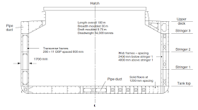
Now the hull form of a bulker is generally cell-guided to account for its longitudinal strength (for larger ships) and is web framed (in shorter ships) to account for its transverse strength. The basic design of the hull form of bulk carriers is mainly comprised of a thick double shell plating and girded by tanks in the sideways, bottom, and top zones. 

Strength of The Hull Girder


The double bottom structure not only adds to strength of the hull girder and protect the bulk cargo inside from any kind of oceanic disturbance. It also provides a protective layer against accidental flooding, breakage, leakage or grounding of a ship.

Double bottom structure (Solid floor and Bracket floor arrangement)
(Copyright: Ship Construction, D.J. Eyres)

The elaborate arrangement of tanks with the double bottom tank below, lower hopper side tank or bilge tank at the bilge or the upper hopper side tank underneath the corners of the upper weather deck mainly account for the ballasting systems in ships. Ballasting is an operation done by the intake of some amount of freshwater or seawater in the tanks for the purpose of maintaining the stability and buoyancy of the ship (hence maintaining its centre of gravity in diverse sea conditions). The tanks also have manholes for the purpose of surveying, discharging, repairing and maintenance. 

The deck and hull elements have an elaborate arrangement of girders and stiffeners for providing longitudinal strength.These may be welded or riveted depending on their location both in transverse and longitudinal direction.


Midship Section of a single skin bulk carrier. (Copyright: Ship Construction, D.J. Eyres)
Midship Section of double skinned bulk carrier.
(Copyright: D.J. Eyres)

Cargo Handling


Bulk amounts of cargo in bulk carriers may be loaded and unloaded by the virtue of large openings in the deck known as hatch openings. These openings are generally less than half of the beam (< B/2), generally one-third in single hatch ships and 0.75 in double or more hatches. These hatches are covered by hatch covers and have coamings which protect the cargo from flooding and damage in high seas and also accounts for compensation of loss of strength of the deck due to the openings.

The hatch covers may slide, fold, roll or be guided by hydraulic lifting systems. Some special techniques as in the pontoon decks may be adopted. All such designations are in congruence with the load outlines and the structural necessities of a ship.

Folding, Single Pull and Direct Pull hatch covers.
 (Copyright: Ship Construction, D.J. Eyres)


Rolling hatch covers.
 (Copyright: Ship Construction, D.J. Eyres)

Specialized cranes and derricks may be used for loading and unloading.  A crane's discharge rate is limited by the bucket's capacity (from 6 to 40 tons) and by the speed at which the crane can take a load, deposit it at the terminal, and to return to take the next. For modern gantry cranes, the total time of the grab-deposit-return cycle is about 50 seconds. It may also be of self-loading or self-discharging type where the process of loading and unloading may be by the use of conveyor belts where the loading and unloading rates may range from 100 to 700 tons per hour where the most advanced ports have a range of up to 16,000 tons.


Cargo handling arrangement on a bulk carrier with 4 cargo holds.
(Note how one derrick is used to operate on two holds)

Cargo handling arrangement of the same bulk carrier above, in plan view.
(Note how one derrick is used to operate on two holds)


Proper surveillance and checking methodologies are adopted for the cargo both ensuring its quality and the stability and safety factors of a ship. Grain shifting is an awkward and often dangerous problem in case of dry bulk, where the unpackaged or loosened cargo pose the problem of shifting when exceeding the angle of repose mostly due to lack of levelling or the heavy sea conditions. It leads to the loss of stability and precarious rolling motion.

If you observe the slope of the wing tank plating, it has a reason. This angle differs in different bulk carriers, matching the angle of repose of the cargo that is to be carried. If the angle of the wing tank plating matches the angle of repose of the cargo, then cargo shifting is considerably prevented.

Machinery (In Brief)


The machinery and the engine room is aft near the stern for proper control and also for maintaining the trim. Most of the common bulkers like the Panamax or Handymax have 2-stroke heavy duty diesel engine attached to a fixed-pitch propeller. Smaller vessels usually have one or two 4-stroke engines attached to the fixed or controllable pitch propeller via a reduction gearbox.


Engine Room Arrangement at three floor levels above bottom line.

Recent Developments


Bulk Carriers, being the workhorses of the maritime economy have come a long way through disasters, losses, and hazards. So, with the passage of time, especially after the tragic loss of MV Derbyshire, the IMO, and the other International Safety Organizations have become more cautious about safety measures to be taken in a bulk carrier. Though, it lists out to be huge, some of them are:

  • A stronger double-bottom accounting for more stable structure.
  • At least two or more holds watertight are necessary to avoid heavy trim in case of accidental flooding or leakage.
  • Improving hatch structures and coamings, so that water does not enter the holds even in heavy seas.
  • Generally it is difficult to assess loading conditions and heavy lifting operations are usually slow (it can take over an hour just to halt the operation), occasionally resulting in overloading the ship. Sometimes, unexpected shocks, over time, can damage the hull's structural integrity. 
  • Much more care is taken and advanced techniques are adopted for maintaining proper angle of repose and preventing grain shifting and also to keep the cargo evened out. 
  • Corrosion, due to a lack of maintenance, affected the seals of the hatch covers and the strength of the bulkheads which separate holds. The corrosion is difficult to detect due to the immense size of the surfaces involved. So more care is taken to prevent corrosion and prevent life span of the ships. 
  • Improved ballasting technologies. LSD


Article By: Subhodeep Ghosh     


Sunday, 12 April 2015

In Depth- Wave Making Resistance (Part One)

Today, let us learn in depth about an important component of a ship’s resistance. The component here which I speak of is the wave making resistance. Now, before trying to understand about Wave Making Resistance, we need to know one thing about waves which are basically gravity based phenomenon. The first thing necessary for wave generation would be a free surface between air and water. 
These interfaces would be what would give rise to waves owing to pressure differences. These pressure differences are a result of the interaction of the fluid streamlines with the ship shape at the fore peak which causes reduction in the velocity. This means a rise in pressure has occurred (Remember Bernoulli’s Theorem?) at this point. We will call them ‘Pressure Points’ from now on. Let us not consider flow circulation and vortices around these slopes for now.
Fig. 1:A pictorial representation of the various terms associated with the wave generated from passage of a ship across water (Courtesy: http://www.ifm.zmaw.de/ )

When a ship or for all normal purposes, a body moves in a fluid, the surrounding layer of fluid exerts pressure normal to the surface in contact with it. Now, assuming the situation to be an ideal one, where the fluid is non-viscous (remember, viscous to fluids is what friction is to solids), we observe that the pressure components hog the body from all directions and so their normal components cancel out eventually. However, this is not the case with viscous flow in real fluids as we will see now.
In a viscous medium, the pressure at the forward end and the aft end will be more than the middle body of the ship. This is because the water when flowing across the ship encounters the slope of the fore peak of your ship for the first time, causing the pressure at this point to rise. Now, the flow could have continued along this new path as shown below, no trouble here, but we shall ‘close’ the shape of our ship here and this calls for another slope around what we will now call the ‘forward shoulder’ of our ship.

Fig. 2: The wedge shaped model used to analyse the wave systems generated by the body when travelling in a fluid. These observations hold in the same way for a stationary body in a moving fluid too.
Actually, a more appropriate visualization would be to consider our ship half-breadth as having 4 distinct pressure points-2 at the fore and 2 aft of the middle body which is predominantly continuous without any steep slopes. Yes, two peaks and two shoulders. The pressures are positive at the peaks and negative at the shoulders. Remember this assertion.

Now waves are composed of crests (elevations) and troughs (depressions). The forward peak and the aft peak ‘wave systems’ originate from crests and the shoulders (fore and aft) from troughs. The ships waves are generated as a superposition of ‘wave systems’ generated at different pressure points on the ship’s water plane. A model used to describe this is the wedge-shaped boat model as schematically represented below. There is another symmetrical pressure disturbance which is often considered together with the wave systems in many texts is given separately below here.


Overall Wave Systems


The work of Lord Kelvin gave a better physical interpretation of wave making in ships. He considered these ‘pressure points’ moving on the flat free surface and gave a theoretical explanation for the wave systems generated. Two sets of wave systems are generated, one being the transverse wave system, the other being the divergent wave system. Take a look at the image below for the same body moving on the fluid from different perspectives to get a clearer idea.

When observing from a ship, what you would perceive would be the combination or superposition of the wave systems described above and so the most prominent bow wave system would be primarily perceived.
Fig. 3:Photo of a ship taken with the wake pattern clearly showing the turbulent component of wake in the middle. (Courtesy: www.bit-player.org)

The Divergent Wave System


Kelvin found that the divergent wave system would be contained by two straight lines originating from the pressure point which in this case is roughly our slender ship moving on a vast ocean. The angle which one of these straight lines would make with the centreline of the vessel was found to be around 19 degrees 28 minutes. This would continue to propagate way aft beyond the ship. We will talk a bit more about this divergent wave system the next time.

The Transverse Wave System


The transverse wave system would be perceived when viewed about the mean sea level. This wave system constitutes the major part of the wave making resistance. As it is left behind far aft of the vessel, the wave height becomes shorter and the wave length longer.

Both these systems move with the ship and might appear stationary to an observer aboard the ship.

What Next?


Fig. 4:The Kelvin Wake pattern clearly observed for a boat. (Courtesy: Wikipedia/Edmont)

The wave making component of a ship’s overall resistance adds to the power consumption. In simple words, we cannot afford to allow the ship’s power go into generating waves and this is difficult to avoid in ship design. However there has been extensive analysis and now Naval Architects can put the science behind the phenomenon to use in the design of the  propulsion based on certain features.

We shall talk a bit more about this component of the ship’s resistance next time in the sequel to this article.LSD

Article By: Sudripto Khasnabis

Sunday, 5 April 2015

The Flip Ship

Imagine staying inside a room which would tilt itself square as and when needed. You might think such things sound good in fiction and not in real life, but if I tell you that designing such a room or in our case, a ship or platform has it's unique advantages, especially for Oceanographic Research.

Read on. Yes, there exists a platform that can flip itself on its own.

Fig. 1:R/P FLIP
(Courtesy: www.google.co.in)

You and I just wonder of her design, but there were these two MPL scientists, Dr. Fred Fisher and Dr. Fred Spiess who designed FLIP in the 1960's out of a need for a research vessel for studying acoustics of submarine rockets for The US department of Naval Research.

This baseball bat shaped ship of about 700 GT is a remarkable example of engineering technology.

The open ocean platform, R/P FLIP (Floating Instrument Platform) owned by the U.S. Office of the Naval Research (ONR) is  operated by the Marine Physical Laboratory (MPL) of the Scripps Institution of Oceanography. 
Serving her purpose for more than 50 years since 1962 when she was launched by the Gunderson Brothers Engineering Company in Portland, she has given her significant contribution to oceanographic research.


What do you think created a need for designing a vessel that can flip?


As the saying goes ..'Necessity is the mother of invention'.

Carrying out research in open sea is really a tough job. There are interactions of the vessel with the wind, with the current and tides. This makes it difficult for a vessel to maintain its position. For effective collection of oceanographic data, it is important to focus on the design aspects of the vessel. This is where R/P FLIP stands out differently. The vessel in such a mission should be wisely designed such that she has good stability even in rough seas and capable of maintaining its position even in high waves.

There should a considerable difference between the vessel's natural period and wave period so that there is minimum effect of waves on the scientific devices used while measuring oceanographic data.

After conducting a number of experiments and considering several configurations for the desired hull form, aiming for easy accessible working deck space and stability of FLIP in both horizontal and vertical positions, the design was finalized taking into account the arrangement of sensors and other scientific equipment to be placed on board.


Fig. 2:FLIP in vertical position
(Courtesy: www.google.co.in)

In her vertical position, the FLIP has less wetted surface area compared to that in horizontal position, this reduces the frictional resistance acting on her hull. Wave loads acting on it are reduced causing less motions of the vessel.  


Following were some of the requirements for design consideration of the FLIP:


  • The hull of FLIP ship is specially designed to reduce the torsion effect when acted upon by water pressure. 
  • Acoustically quiet for avoiding unwanted acoustic reflections when ballasted.
  • Flexibility in terms of space for mounting and movement  of scientific equipment on board.
  • The location of underwater hydrophones should be easily traced.
  • Shallow draft of 15 feet and 300 feet draft for placing of hydrophones.

Fig. 3:FLIP towed to research site
(Courtesy: en.wikipedia.org)

You must be wondering why a 108 meters long FLIP which partially floods does not have her own propulsion system?

Well, the reason is interference of propulsive devices with her highly sensible acoustic devices on board. For this reason, FLIP needs to be towed to the research site.

A hydraulically operated propeller at the tail end rotates the FLIP about her vertical axis.

What do you think might be the reason for tapering spar design of FLIP? The spar tapers from about 6.5 meters diameter at 91-49 meters depth to around 4 meters diameter at 20 meters depth. Think of it relating to oscillations of the structure.

The varying diameter of the spar shape is useful in giving less response to wave motions. This can be understood when the vessel moves less than a meter in a 10 meter wave height.


Equipment deployment


A wide range of scientific equipment including sensors can be deployed by the FLIP.


Fig. 4:FLIP in operation
(Courtesy: www.google.co.in)

Also, with the help of variety of booms and winches, sensors can be installed at different locations on the submerged hull which has attachments for their placing. This positioning of sensors depends on the weights and types of sensors.

Ambient noise measurement is done using vertical hydrophones that can be placed at different locations and horizontal hydrophone arrays (DIMUS) at bottom of hull.

Wondering how sensors are laid on ocean floor?
This is done using a fair lead attached to the bottom of the hull, which can deploy 3000 meters long array of sensors. Up and down motion of Meteorological instruments on the boom helps to collect data near the water surface.


Fig. 5:Scientific equipments on FLIP
(Courtesy: www.apl.washington.edu)

High resolution, narrow-beam array Doppler sonar employed on board measures wave motions in about a cubic kilometer of surface water and with lowest and highest frequencies wave motions upto 40 meters depth can also be measured. The figure to the left shows variety of scientific equipment on flip.


So how does she work?


Is there any special advanced mechanism for flipping? If so, how it was possible to build it with that advanced technology almost 50 years ago? Many such questions will be arising in your mind. Let me introduce you to her working, I m sure working of such a unique ship has already generated curiosity in you.


The FLIP works on the concept of ballasting. Yes, it is this simple concept that gives her uniqueness. The concrete ballast provides buoyancy in horizontal position. It is as simple as when a body is filled with water it submerges. So now it is easy for you to understand its working.
  • The hollow body of FLIP first deploys anchors when towed to a research site.
  • Then with the help of ballast tanks of capacity of 9 tons of water weight located in long thin handle of vessel, ballasting of tanks with sea water is carried out.

Fig. 6:Rotating FLIP
(Courtesy: blog.kineticarchitecture.net)

  • Now, one end of FLIP has more ballast, causing it to sink, while the other end is filled with air. This process lifts the barrel equivalent to 5 storey out of water and the ship slowly becomes vertical. Most of the buoyancy when flipped is provided by water at depths below the influence of surface waves. Diesel engines with a combined output of 340 kilowatts makes this possible just under 30 minutes.
  • When the operation is carried out, setting the ship back to her horizontal position is another difficult task but its just the opposite of what we learnt above. It means de-ballasting the tanks with the help of about 3000 cubic feet of compressed air (stored at 250 psi ) forces water back out and FLIP is again brought to her horizontal position taking half the time needed previously.
All this happens without disturbing the scientific equipment which are stored in cases mounted on walls.
Fig. 7:Ballasting of tanks during flipping
(Courtesy: www.amusingplanet.com)

Designed for operating safely in both shallow water as well as water depths exceeding 2000 meters, the lowest exterior of FLIP is about 15 feet above the waterline when vertical. You will be glad to know that  FLIP is rated to handle even massive 80-foot swells.


Fig. 8:Interior designed for both horizontal and vertical operations
(Courtesy: www.dailymail.co.uk) 

Have you wondered where do the crew stay during flipping? its like an amusement park ride for the crew and riders as they remain on the external decks during the flipping evolution. The wall becoming ceiling after flipping, interiors that are curved or which can flip 90 degrees, heavy equipment like generators mounted on trunnions are some of the specially designed features of the FLIP. 


Operations


Out of a home base at Scripps' Nimitz Marine Facility in San Diego, California, the normal area of FLIP's operation is off the west coast of the United States. 

FLIP also supported research in studying wave heights, water temperature and density, collection of meteorological applications like variations in properties of earth's crust, study of ocean floor using Doppler sonar, energy transfer between atmosphere and ocean, pressure variations and its effects on wave properties, reverberation etc.

FLIP contributed for a set of experiments called High Resolution Air-Sea Interaction project, which measured wind and swell conditions. That data is helping to improve weather models and other ocean-atmosphere databases.LSD

Article bySiddhi Indulkar